MC4X15A Motor Controller

mc4x15a_2

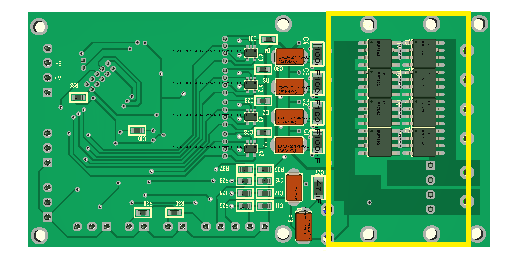
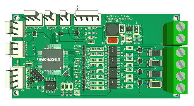
This Motor Controller is still a bit of work in progress, what is remaining is the communication parts and a review of protection logic. The actual challenge here is size. I am mounting components on both sides to get it small, but as it get smaller the PCB routing get far more advanced. I am a bit surprised on how much easier it was with the Communications adapter and 3xAxist Mini Stepper to just use a bit of extra space and use single side assembly.

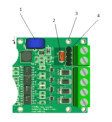
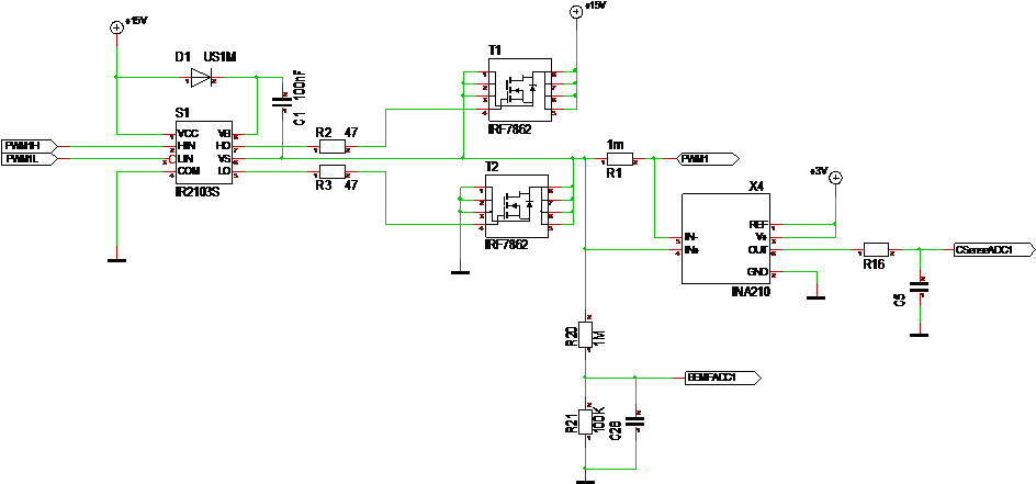
  1. 4 x Half Bridge Drivers
  2. 5-36V Power Connector
  3. Current, BEMF Sensors, Gate Drivers. HEXFET’s on opposite side.
  4. STM32F405RG w/ full BasicPI SWD connector.
  5. Space for communication parts. RS485 added, Ethernet and CAN being considered.
  6. 3.3V Switched PSU
  7. Hall sensors.
  8. 2 x Temperature sensors.
  9. End Stop Connectors
  10. Resolver/Encoder.

I have reserved pins for Ethernet, CAN and RS485 simultaneously, but I am not sure wherever to add it all or not. In addition to that I want to add a SPI port for “disk”. I am considering several options. Adding a SPI Flash is straight forward, but I am toying with a few ideas around having an embedded SSD solution.

A sharp eye will observe that the stand-alone driver is embedded into the controller. I will make a separate PCB later.

VNH2SP30 – 30A Motor Driver

vnh2sp30

This picture is a Dual DC-/Stepper- Motor shield for Arduino. It is available on various sources for ca 5.- USD +/-. The Picture is borrowed from one of the shops on AliExpress.

The interesting thing about these monster chips is that they are full H-Bridges capable of working up to 40V with a 30A continuous output. The only drawback is that they are 5V design on signals, but we can add level shifters to deal with that. I have failed to find a 3.3V version. The trigger level is 3.25V so a 3.3V signal might work by accident thought.

The chip shown is VNH2SP30. You will find loads of notes and design on this chip on the net as they are very popular for good reasons. They also provide a very easy path to a straight forward 30A stepper motor.

The size of the chips are however actually larger than the total area I use on my own using discrete components, thought I only target 15A. But, as stated before you need to deliver the current to the motor as well. I actually want to buy one of these for testing.

3.3V Switched PSU

3v3switched

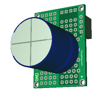
This little fellow have the same layout as a classic 7805 and is a 35V to 3.3V switched regulator capable of 600mA. The circuit handle 42V, but the capacitors will limit the circuit to 35V I think. I just fancied making this as a bread-/vero-board breakout. The entire circuit is 20×10 mm and occupy less space Integrated on a PCB. The schematic is included below. Sorry for the weird component numbering as this is clipped out from a different schematics.

3v3switchedschematics

3-phase Micro – cable issue

20161217_091130

I was initially quite happy with the way this cable fitted, particularly as I found a trick on how to solder these. But, this is how it looked after having fiddling with it for a day. I could add a proper micro match connector, but they are a bit expensive.

micro-cable

Another solution is to add a cable holder on the PCB at the end to avoid that handling the cable is exposed as stress on the solder points. In this case I need this cable since I am connecting to a motor with a special connector, but for the micro PWM driver that have the same issue it might be an option to simply use 2.54 pitch connectors. It is nice to have things small, but they need to be functional as well. The challenge is to find a solution that is practical and don’t drive size or cost to much.


Backfiring 3-phase motor

Reviewed the design today and the issue is that the way I am testing easily unleash spikes on several hundreds volt since I disconnect a coil with energy in it. The voltage can be extremely high even if it’s close to no energy in it. Two solutions are suggested (1) avoid disconnecting the motor while it is running, or (2) add protection circuitry if I insist on doing it.

What I plan is to use the 3.3V from DRV10983 to drive the hall sensors. This will then be a separate 3.3V from the one driving the MCU. Secondly I need to add at least 4 TVS diodes which is easy since I am using a small, nice array of 4 x 6.1V diodes that would have done the job. Again this should not happen in normal operation.

3-Phase Micro – motor backfired

20161216_003916

Finally got around to solder on the DRV10983 3-phase driver and start testing – result one busted MCU. The PSU is still alive, but the board suddenly use ca 1A with an overheated, dead MCU.

I just used the Speed and Dir pins for now. The motor ticked around, but as I disconnected the motor with power on it backfired and damaged the MCU. This is a naughty way of testing, but it does its job. This is not the first MCU I break this way. I did not expect this motor to have sufficient energy to create this problem, but lesson learned.

The motor ticked around both directions. DRV10983 showed no sign of heating up, but the motor did get a bit warmer than I expected. I think this is parameter setting or me pulsing it wrong – we will see as we connect the I2C later. It ran’s nicely with acceleration and everything.

It’s a reminder of how nasty these motors can be if they backfire. Will replace the MCU and disconnect the hall sensors for more testing later. Will make a vero-board connecting between the micro and motor to add the extra bits we need – this will also enable me to scope the Connections so I can see what is going on. I suspect I have underestimated the hall sensor circuit as this is on the same 3.3V that drive the MCU without any protection – but we will see.

3-Phase Micro – printf

serial_printf

int main(void)
{
  int x=0,y;
  char buf[100];
  AppInit();
  printf(“\nBasicPI Micro 3-Phase Controller!\n”);
  while(true)
  {
    nanodelay(1000000);
    printf(“%d tick\n”,x);
    x++;
  }
}

The 3-Phase micro controller use a RS485 (RS-X) connector. I have not enabled the RS-X package yet, but I always start with a simple printf implementation and a terminal program. This is in 99% of the cases the only debug I need. It will be implemented on top of RS-X as well. Just nice to see that the MCU actually is ticking before we start digging into running the motor – this gives me eyes to look what is happening. My apologies for the formatting of the C main above – I need to find a better way to show source code annotations…

New PCB fun

20161215_194403

Two more PCB’s arriving from factory. The large board is the communication adapter. This is so far the most complex board I have made so will be a bit of a job to test it out step by step. Happy to see that RJ45 and USB connector fit correctly. The red board is the mini 3-axis stepper controller.

The challenge I have is that I have so many ideas that I can easily spend the next two years doing electronics, I seriously need to get my act together and complete the software packages as well – and not only the testing/proof of concept. My collegues look at me with strange eyes as I mention that I find making Electronics relaxing 🙂

20161214_224541

This last is the 3-phase micro controller I have shown before. I actually had to order the DRV10983 chips twice and I have really been waiting on these ones. The first lot got stuck in customs so the seller want me to take a refund. I have a package of STM32F042F6 sent the same time from a different seller that is missing. I order most of my stuff from Asia and as I have mentioned before I seldom loose out – if I do it is usually the postage system in Norway that is to blaim.

The large chip at left is DRV8301, a 3-phase pre-amplifier. I decided against using this for now because I wanted the 4th Half Bridge driver, but also because I fear this chip ends up beeing a bottleneck on a 2-layer PCB as everything needs to be routed in/out on this. But, we will put it to some usage later. Fun for later – this is getting too exiting with too many things to try out – xmas fun 🙂

3.3V Switched PSU – LMR14208

3.3V PSU is always a challenge on small PCB’s. I tend to end up with linear regulators due to size and cost. They are are great, but regulating from 24V to 3.3V means you use more effect on the regulator than you get out. Sometimes I also need to regulate to 5V and continue to 3.3V. I seriously need to move on to switched PSU’s.

d24v3f3

The circuit above is D24V3F3 from POLOLU giving 300mA. It’s 13 x 10mm, but it cost 8.- GBP on ebay and 5,5 USD on hobbytronics.co.uk.

lm2596

This is a larger one based on LM2596 that can regulate from 1,8 to 36V with 3A or so output. The breakout board can be bought for ca 50 pence on ebay in bulk. I use these a lot because they are great and I can’t even buy the components for that price. 3A is however far more than I need, 300mA is probably ok. An MCU usually tick on 10mA, but transceivers for RS485, Wifi, Ethernet etc tend to use a bit more.

Looking at making a similar circuit myself I found LMR14208 from TI that comes in a thin 6 pin SO package and delivers 600mA. The reference schematics only use 8 components all included handling input voltage up to 42V.

lmr14206

This schematics are from LMR14208 datasheet and it also contains examples for 12V, 15V and 0,8V. I need to find a diode and coil, but it should be very doable to implement a Switched PSU using the same space as the POLOLU one with 600 rather than 300mA. LMR14206 is sadly priced around 1.- USD from the Sources I have, but well – can’t always win.