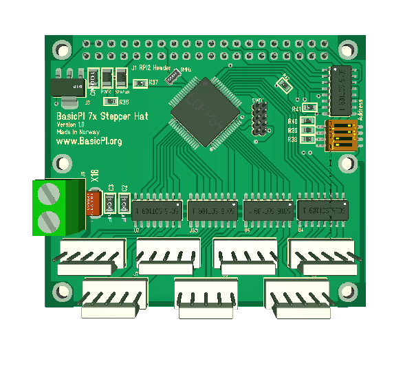
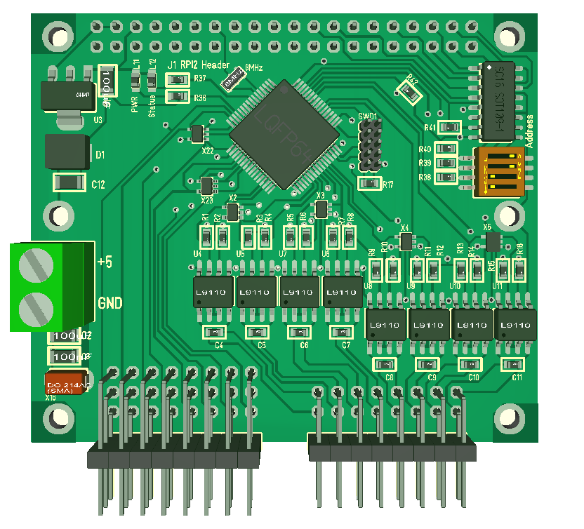
32 x Servo Hat – PWM Resolution

What “PWM” resolution will the 32xServo Hat Use? 

I have not given the question much concern, but I notice that someone advertise 12 bit resolution on similar products. I tested the same Circuit they use earlier and decided against using it because it’s I2C interface was to slow in making multiple servo position changes simultaneously. I simply could not move my robot the way I wanted, so lets look into the details.

The 32xServo Hat uses a M3 72Mhz ARM that only sit around to clock channels. So my resolution (position accuracy) is depending on how fast and reliable I can tick through a 32 entry table. 12 bit resolution means 4096 positions while we can estimate at least an iteration per 0,1 ms giving 10,000 positions. If we really need to we can probably add a zero to that.

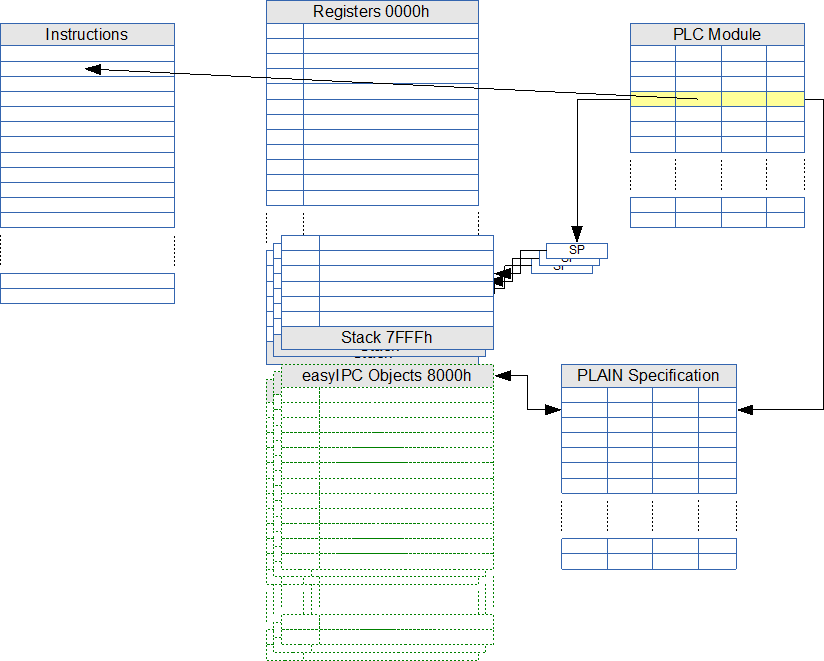
The second question is more interesting – how fast can we change all 32 channels if it is part of a combined movement? And can we pre-store complex operations on the Hat?

This is the thing – we do have a powerfully MCU so we can program intelligence into the Hat to avoid that RPI needs to do low Level operations. Data transfer rates are fast so we can set 32 new positions within a single command using max 10ms from writing it on the PI until it is effect on the controller. This is crucial for more complex robots. The difference is not the speed of the SPI, but the fact that I can do it in a single command on 32 channels due to the design of easyIPC.

Returning to more complex operations – I think we should add a micro-script allowing the Hat to store pre-loaded operations – We actually got 20-32Kb SRAM we can put to some usage because it is more or less unused right now.

32xServo Hat Revision 1.1

32xservehat_1_1Not very exiting, but it has taken me most of the day. This is the revision 1.1 of the 32xServo Hat. Just for the record – the red lanes are actually ground plane so it will all be covered with GND – I just switched it off for the picture.

  • Added optional TVS diode on PSU for better protection.
  • Added 100uF and 100nF capacitor on PSU for spike cutting.
  • Adjusted pin header positions to better fit 3×4 headers.
  • Adjusted the lower 16 channels as they where a bit close to the bottom edge.
  • Added TVS on all 32 channels for protection of the MCU.
  • Changed all LED’s to 0603 package.
  • Added weak pull-up on nRESET.

32xservehat_1_13d

The lower 16 channels can use 3×4 right angle connectors allowing the Hat to be used in a stack. I finally found a good price on 3×4 right angle down to ca 10 cent each – still looking. You can still use classic 2.54 Pitch pin headers that is even cheaper.

Revision 1.0 is actually ok to go, so I will try putting this into production & sales since a lot of people have asked for it. It will be exiting to see what assembly prices I can achieve. PCB & Components are probably ca 10.- USD all together.

Embedded Query Engine

Permanent storage of configuration and run-time parameters is not straight forward with small, embedded solutions as the build in Flash only allow large pages and have a limited number of re-writes intended for program download only. Older MCU’s used a build in EEPROM for this purpose that have been removed from modern MCU’s, so we need to solve this ourselves. W25Q16 is a typical solution using a SO8 package to provide a 16Mbit SPI Flash that allow pages as small as 256 bytes to be written.

The SPI interface will in this case use 6 pins. I have been toying with the idea to create an embedded “disk” that use ca the same footprint as a SO8 as a connector, a 2 pin UART as interface with an offloaded query engine.

embeddedstorageblock

The block diagram above illustrates the idea. We use some kind of storage that can be Flash, FRAM, EEPROM, SD Card or maybe a USB  stick or even a proper hard-disk. Using an UART as interface we create a query engine capable of storing an retrieving data without the host using it’s time. PSU is basically 3.3V from the host with an added sensor to detect power loss and a super capacitor enabling a few seconds operation so we can Flush SRAM out to the storage.

UART is my preference in this case because it is straight forward and available on every MCU in my target range. USB is seldom accessible and even SPI ports are limited and often needed for other things. Using a crossed TTL Interface directly we have a full duplex communication on several Mbits directly.

I can use the SWD connector I designed earlier for this, but we probably should use a 2.54 pitch 4-wire connector and allow for a few cm of wire. If we add a M2 mounting drill hole we can locate the “disk” on a convenient place.

Using a separate MCU to off-load data storage and retrieval basically work the same way as sending SQL to a server. With a bit of clever query algorithm we should be talking about a read/write time < 1mS almost independent of query complexity or data amount (within reason).

ed16m

 The 3D model above is an early draft of the Embedded Query Engine to get an idea about actual size.. This is based on the STM32F030 and the supecap we used on the motor controller. I copied some diodes as well just to get an idea. This is single side assembly and I prefer to keep this simple. I can probably find smaller supercap and diodes for a start – but as always – work in progress – for now it is just an idea that is funny to play around with. Notice that most of the space is related to the supercap.

Visual Studio on Raspberry PI & STM32

visualstudioraspberrypi

This is a dumb blink demo with a console output just to show that it actually works. I have used Visual C++ and later Visual Studio since 1995 so I am not surprised that things work smoothly. A few buttons on my PC to install this, a sudo command on raspberry pi and it just Works. The demo runs on my Raspberry PI 3, but the printf is re-routed to a terminal window in Visual Studio. I actually have a display and keyboard/mouse on the PI as well, but don’t really need one for non-display Applications. Single step debugging etc Works fine – almost as if you develope a Windows app.

I had to use VisualGDB for STM32, but the same experience. This makes my work on software so much easier because I can use Visual Studio for everything. VisualGDB is a commercial solution, but at 79.- USD I will consider a license – though I will considering hacking a free solution because it is actually straight forward.

MC4X15A – Heatsink

mc4x15a-heatsink

Funny how things work out some times. I initially planned for this to be a more narrow board, but had to extend the height to 40mm due to MCU and connectors. This left space unused on top and bottom of the driver making it easy to add mounting holes for an adapter and now a extra set for a 40 x 28mm heat-sink on the back. The red diodes in the middle is taller than the HEXFET’s, so one option might be to mount a space filler and use a larger heatsink with the same size as the PCB.

I want to add a SPI Flash and evaluate options to add a Ethernet before I actually order these boards. As for BEMF I want to add some 100nF Ceramic capacitors to help on spiking, but other than that we should be good.

I also realize that the two resistors mounted on left bottom need to be moved a bit up in case I want to mount the temperature connector bended inwards. At least one of them must go to the HEXFET’s. I have added two temperature sensors to have some flexibility in case I am running two DC motors or want a temp sensor on the motor as well.

Visual Studio for Raspberry PI

One of my main concerns for some time have been to find a free development kit that actually works for Raspberry PI. I intended to develop directly on the PI, but the drawback with that is that I need a 3rd screen + keyboard/mouse and I simply have no room for it as is. The other is that I have lost a few SD cards in earlier trials so I don’t want to save source on RPI. Cross Compilation will solve this.

Long story short – I have tools I use because I have no option and tools I prefer to use. Visual Studio and previously Visual C++ have been among my  main preferences for years. It simply is one of the best IDEs available. With Microsoft releasing the community version it becomes free for people like me, and with the release of GDB support I can install an extension and use Visual Studio on my PC to work on Raspberry PI like any other embedded project. This is a major step forward in making it easy to develop C/C++ for Raspberry PI in my case. And best of all – you download, install it and it just works without any fuzz.

Using add-on’s like VisualGDB I can also move my STM32 development to Visual Studio and get both STM32, Raspberry PI, Android and Desk-top development under the same “rooth”. I noticed comments from Microsoft on their forum indicating that STM32 and other development will be included in Visual Studio – the note was 1 year old.

MC4X15A Adapter Board

mc4x15a_adapterplug

Earlier I had a BEMF issue with my smaller motor controller, so I have been reading up on other peoples experience and solutions to design my own. What I came up with is 3 changes on the MC4X15A.

  1. Added a 0.33F super capacitor on 3.3V protected by a TVS (on the back) at ca 4V. The supercap will absorb any spike that reaches 3.3V and it will allow the MCU to survive a power dip of several seconds. The later is great as it allow the MCU to monitor and record a Power dip.
  2. Protecting the main PSU with a nasty TVS to avoid that it spikes out of control. This will be set just a few volts higher than the max voltage. This diode is also protecting the surroundings as we have no galvanic issolation on this one. This should also protect against wrong polarity.
  3. I need more capacitors on the PSU, but I have no room for these. I also wanted a battery adapter option. I decided to make room for an adapter board supported by 4 extra M2 screw holes that either can carry extra capacitors or a battery adapter. The example (below) show a 10,000uF/50V capacitor, but notice that this in reality is a vero board so you can add your own design of capacitors.
  4. The connector is a standard 2.54 pitch pin header enabling the adapter board to be engineered on a piece of vero-board. I didn’t want to lock to a specific capacitor at this point so vero-board is fine. This also allows a variety of simpler solutions if I don’t want to use the adapter Board.

mc4x15a_capadapter

I am still not confident that I got everything about BEMF 100% correct, but I will work on that. I might need a combination of capacitors as well as more diodes – not sure. And I need to test this so it will be a few exploding capacitors before I am done :).


MC4X15A – High Side Current Sensor

The original current sensor logic will use a shunt between the lower HEXFET and ground (low side current sensing). This is fine for 3-phase, DC or Stepper motors, but it will not enable measuring of current on a single, stand alone Half-Bridge.

An alternative way of doing this that fix this issue is to measure the current on it’s way out as indicated below using “high side current sensing”.

halfbridgewithcurrent

In this schematics we introduce the shunt on the PWM Out and take advantage of INA210 being a high side sensor. I connected BEMF to the left side of the shunt due to routing logistics. With a 0.001 Ohm shunt this error should be constant and very small.

High side current sensing is more responsive to changes in the current flow and adds no disturbance to system ground. The main disadvantage is that because the shunt resistor is not at system ground, a differential voltage must be measured which requires the precise matching of the proper differential amplifier. However, this disadvantage is eliminated with the use of a precision current shunt monitors like INA210 or similar.

mc4x15a_091

Transporting the current out proved to be easy as I mounted the shunt opposite the high side HEXFET using it as a path out. The disadvantage is that as the HEXFET heats up so will the shunt. If this becomes an issue I will extend the length and move the shunt to the right. INA210 is mounted opposite the low side HEXFET and will have the same issue, but reading the datasheet it should have max ca 1% temperature drift error. Current sensing is most critical for 3-phase control, but keep in mind that we measure all 3 phases. As adding all three phase currents should give 0 (zero) we have a sensor error indication implemented.

32 x Servo Hat


20161226_232805

Finally had the time to assemble a 32 x Servo Hat. Have not written any code for it yet, but always nice to see SWD answering and led’s coming up with a 10mA current on the lab psu – Things look normal. Will get down to wrapping up a servo controller and assembling a RPI with an user interface later. I will be using RPI3 because of it’s build in Wifi to control my robot.

The MCU on this is STM32F105RB, so it got plenty of juice and IO. Controlling Servos and motors are obvious, the channels can also be used for digital I/O and analogue I/O.

20161226_232910

The picture above show the SWD adapter connected and illustrate why I need to modify this to go out as a thin board horizontally. I only mounted channel 1-16 for now due to the space conflict with the adapter.

20161227_010222

This last picture show the 32xServo mounted on Raspberry PI 3. It can be stacked with an extra spacer or by mounting it at top. If stacked you can control 8 x 32 = 256 servos. More interesting is probably the capability to combine Hat’s to make Advanced systems.

MC4X15A Stepper-/BLDC-Motor Controller – Revision 0.9

mc4x15a_top

First actually finished draft. I call it 0.9 because I plan some minor changes before I send it out. Firstly the size did not work out as expected. I ended  up using 40mm width due to the MCU and mount holes. I first extended it at bottom to get M2 mounting holes. Later I had to extend it on top because routing was getting tight. It’s a combination of all the connectors and using so much of the MCU that drive the size a bit on 2-layer + in this case a bit of bad planning. But, well – 80 x 40mm with all the features added and proper mounting holes is not that bad.

mc4x15a_bottom

This shows the backside of the board. Dense 2 sided assembly on the driver and almost single sided assembly on the rest. I would like to work on the size a bit, but for now I want to move on and order the PCB so I can test lane capability and concepts to move on. The driver area is only ca 40×20 mm.