Programmable PSU 2

SinePWM

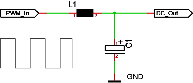
A programmable, switched PSU can also be used as a function generator. The diagram above illustrate how we can change duty cycle of the input PWM to create a DC waveform out. This is actually one of the techniques we use to run 3-phase motors, but it also have the potential to become an awesome lab-PSU with capabilities to simulate spikes/noise or AC PSU’s.

The challenge is however that the frequency out will be ca 1/20 of the PWM frequency in. So using 20Khz PWM we should be able to generate decent waveforms up to 1Khz. This is not much, but it is a OK capability for a lab PSU.

Programmable PSU

SwitchedPSU1

I need to address one more electronic designs – I need a 15A PSU for my robot. I did a vero board design earlier using 4 x DC/DC converters due to their low cost. This delivers 12A in peak which is what I need with 12 x servo’s to allow them all to operate simultaneously. But, it is rather big, so I would like to optimize the size a bit if I can.

The concept of a switched PSU is rather easy – you send PWM into a filter consisting of a coil and a capacitor as illustrated above, and you get DC current out. If you have 12V and apply 50% duty you should have 6V in average out.

I designed a 4x half-bridge driver earlier with a very small driver stage, so what I would like to test is to convert this into a programmable, switched PSU. MCU’s are cheap these days and a small STM32F030F4 costing 50 cent could do the job here. It got ADC’s, UART and PWM output needed. It is worth a try to see what we can get out of this.

The fun of electronics

Just realised that I have produced 15 different electronic designs of which 14 contain a MCU the last 6-8 months. I have several other designs in the planned pipeline, but I am holding back a little because I am getting a huge backlog of designs I need to finish coding for.

The challenge is that I find it very easy and relaxing to drop into the lab and do 30 min ++ on electronic schematics, PCB layout or just write a blog article – and actually get something done in 30 minutes. Software work tend to be the larger and more invisible part of the job once the high level design is drafted.

Plain Assembly – parameters

Developers of C/C++ will probably be a little confused over the lack of pointers. I use syntax like:

Func MyFunc(MyObject ob)

What is “ob”? Am I sending the full object, a reference or a pointer?

Func MyFunc(MyObject ob, uint32 i)
            ob.myParameter = 1
            i=2
End

MyObject foo
uint32 var
Call MyFunc(foo, var)

 In C/C++ this would create a copy on the stack, so any changes would remain local. This is very clear in C/C++ because we control pointers. In other languages “MyObject” would become a hidden pointer with the consequence that the assign inside the function would alter “foo” while the 2nd assign will only change the local copy if “i”.

The idea (for now) is that objects always are passed as a pointer by default, while build in data-types always create a local stack entry.

Func MyFunc(copy MyObject ob, Reference uint32 i)
            ob.myParameter = 1
            i=2
End

This one add a option parameter “copy” to force the object to become a local stack copy in case we need that option. I also add the keyword “Reference” to force i to become a pointer so that changing I will change the oroginal variable. Using “Reference” will generate an error if we try calling this with a constant value.

Plain Assembly – Event triggers

I need to evolve my Event trigger mechanism.

Lets assume we want to control a robot with 2 electric motors – one left and one right. We are currently running forward with 1000 RPM and want to reverse with 10RPM.

Assign leftMotor.direction = reverse
Assign rightMotor.direction = reverse
Assign leftMotor.speed = 10
Assign rightMotor.speed=10

The issue is that as we make the first assign we also raise the event. This will cause the left motor to reverse at 1000RPM. The result is behaviour we did not intend during the update, so we need a mechanism that allow us to Control the event.

Object Motor
            uint32 direction
            uint32 speed
End

Event C OnCommand(Motor lm, Motor rm)

const Forward = 0
const Reverse = 1

Motor leftMotor,rightMotor

leftMotor.direction = forward
rightMotor.direction = forward
leftMotor.speed = 1000
rightMotor.speed=1000

Raise OnCommand(leftMotor, rightMotor)
...
leftMotor.direction = reverse
rightMotor.direction = reverse
leftMotor.speed = 10
rightMotor.speed=10

Raise OnCommand(leftMotor, rightMotor

“Event C” does in this example declare a C code event named “OnCommand” with 2 x Motor Objects as parameters. Rather than having event’s triggered automatically we raise them controlled. I have tried different syntax to do the same automatically, but I believe controlling this manually actually is a must.

The syntax is a draft – the usage of raise is in this example inconsistent With earlier examples, so I will need to work on that. I also notice that I forgot Assign on the assign statements – this was accidental, but I decided to leave it because I am considering dropping the need for Assign, Call and Raise in the Assembly syntax.

Plain VM – Distributed Processing

One of the key objectives with Plain is to support distributed systems. The mechanism to do so is at the core of the VM and this is one of the areas where the VM really makes sence.

We have already described objects – data structures that map into C code with Events. We have briefly mentioned that the same mechanism can be used to communicate with a different module – meaning that if you write to a register in one VM instance that becomes an event in a second VM instance – and the two modules communicate.

The beauty of this is that we can do that with easyIPC in the middle communicating between two Plain applications running on different devices – or even better between a C/C++, Java, C#, Python or any application with a easyIPC SDK and any Plain application.

The beauty about it is that it requires close to no extra coding except mapping up events. I need to work on adding syntax to support this, but it will work.

Plain Assembly – Data types

The VM is designed to control logic so everything is mapped into a 32 bit virtual register for simplicity. The assembly language support a large range of data types, but the VM will by default treat everything as a 32 bit register to keep it simple and fast.

The assembly language do however support a range of data-types:

Bit A single bit data-type that can be used to create bit-fields. Used in math it is treated as an unsigned integer.
Byte A byte is 8 bits.
Uint16 An unsigned 16 bit integer.
Int16 A signed 16 bit integer.
Uint32 An unsigned 32 bit integer.
Int32 A signed 32 bit integer.
Float32 A 32 bit floating point.
String A text string.
bool A boolean value that can be true or false.
Object Data structure used to create data-types based on existing data-types.
Enum A data-type that only allow a of constant values.

Arrays are supported for all data-types by adding [] after the variable name. Operations can use ranges as a[0..9].

Adding “packed” to a Object will force it to be bit-packed. This is designed to allow the VM to encode/decode bit-packed Messages etc.

As for other data-types we could also support double64, uint64 etc.

Plain Assembly – End

I just realized that I probably can optimize the assembly a little by introducing “End” as a single entry instruction. The reason is because we now use goto that are 2 entries. I can avoid the 2. entry by using the stack.

for x=1 to 10  
            nop
end

As “for” is an instruction it can create a ix to itself on the stack and as we reach “end” we treat that as a “goto ix”. The upside of this is that we suddenly have a 1:1 between assembly and actual instructions. I also believe this will be faster than using a goto – not that it matters.

if A = 1
            nop
elsif A=2
            nop
else
            nop
end

In this example we introduce “end” to replace the goto’s we only need to insert the ix for the next instruction located after “end”. in this case we would save 3 entries and be down to 10 + 3. The rule here need to be that we insert the ix if we execute the true block. The irony in this example is that we insert “end” before elsif and else, but not at the end statement.

So in short assembly that require a end will insert a ix on the stack that is removed by end as it jump to this location.

Plain Assembly – bloating factor

I will need to look more into the examples and high- and low-level syntax later, but I basically want the assembler to be almost a 3. generation language. What I will do next is to revisit the instruction set to see if we can improve this a bit. Looking at the previous examples I get the following number of 16 bit instructions used:

If example 12
For example 8
Assign example 9
While example 15
Loop example 2
Exit 1
Raise 10
Call 10
Return 1
Encode 4
Decode 4

This is not exact math, but this was 21 lines of high level code that caused 76 x 16 bit entries in our instruction array – and ca 23 actual instructions. Using that as an indication we can expect as many instructions as we have code lines and an average of < 4 x 16 bit entries per code line.

This means that I can expect a 50 line program to be ca 200 entries in an instruction array (or 400 bytes if you like). I need to analyze an actual module with data and map usage to verify this. This number will improve since data and mapping don’t create instructions.

Plain Assembly examples

I used a bit of space on If, so I will just quickly draft the rest of the instructions in High Level Assembly syntax and Low Level Assembly syntax assuing I need both – we can discuss the draft and possible changes later.

For loop

for A=1 to 10 step 1
            nop
end

Low Level Assembly:

start     for A=1 to 10 step 1, next end1
            nop
            goto start
end1

The for statement is 6 x 16 bit entries + 2 for the goto – 8 entries.

Assign statement

Assign is will parse an expression and create an executable table that compute that expression and store the result in a register run-time. This is expected to bloat a bit.

Assign A = B + C / D

The parser will convert this into an instruction consisting of op-code and an array of math intructions as follows:

op-code
R1=C/D 
A=B+R1

 Each table entry will take between 3-4 16 bit entries, meaning that the Assign is 7-9 entries in binary code. I will be more exact on this as I dig up some old code on this.

Low level assembly would be as follows:

             Assign R1=C/D, A=B+R1

While loop

A while loop contains an Expression that need an assign statement

While A+B/C > 1
            NOP
End

Low level Assemby example:

 while   Assign R1 = A+B/C
            ifgt R1, 1 next end
            nop
            goto while
end

 Loop statement

Not sure this adds any value, but it is a way to avoid writing goto. We can always remove it later.

High level assembly example

loop
            nop
end

Low Level assembly example

loop1   nop

            goto loop1

Exit

Exit is a single 16 bit instruction that terminate the module execution.

Raise & Call statements

These are identical in syntax, but with a different op-code since Raise do not create a return and Call does. Using Raise on a module is the same as exit with parameters.

High level assembly example

Raise Error(A1, A+B, C)
	or
Call MyFunc(A1, A+B, C)

Low Level assembly example

The assembly need to use assign to compute expressions into a list of registers that can be used as parameters.

Assign R1=A+B
Raise Error (A1, R1, C)

or

Assign R1=A+B
Call Myfunc (A1, R1, C)

Assign will in this case use 1 + 4 =5 entries. The Call/Raise will use 1 op-code + one for instruction to call and 3 for parameters = 5, so they do in effect use 10 x 16 bit entries.

Switch

Looking at the assembly I ditched switch for now!

Return

Single entry instruction.

Encode/Decode

Encode/Decode is intended for bit manipulation. Decode will read a bit and convert it into a 32 bit register, encode will read the register and write the bit Field.

Encode A:4:2 = B
Decode B = A:4:2

These are low level instructions using 4 entries each.