VM – Updated Design Draft

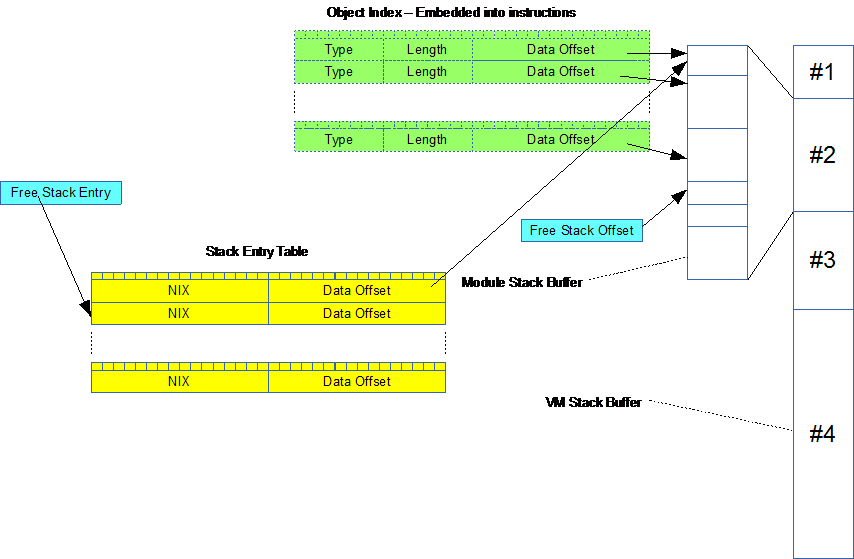
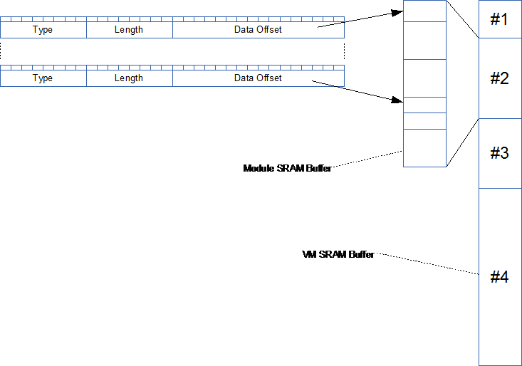
This is an updated illustration of the VM Core. I will not describe it in detail right now because I am in the progress of making proper documentation that will be available.

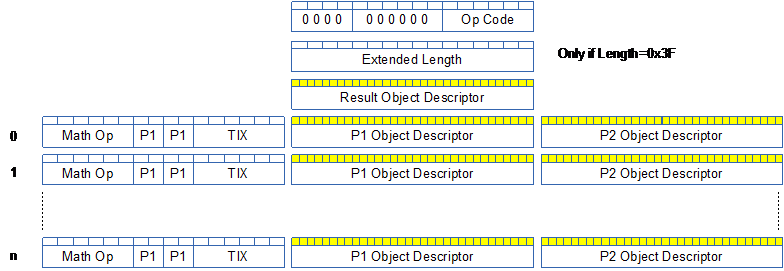
This is the new 16 bit instruction format. I did use a more generic 32 bit instruction set earlier, but concluded that a specific 16 bit was better. Op-Code is reduced to 6 bits and Length is extended to 6 bits. As Length describe additional 16 bit entries it means an instruction can be up to 64 x 16 bit. Only the first 16 bit is mandatory for all instructions.

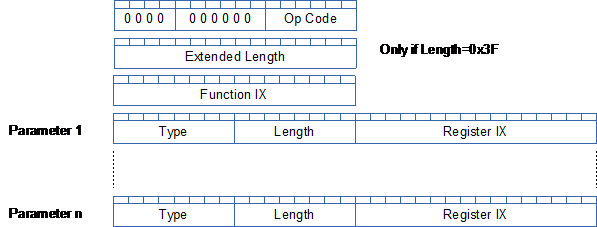
I have also added a 32 bit Data Descriptor. This contains a 8 bit data type, 8 bit byte length of data and a 16 bit register index to start of data. This is used on Call/Raise instructions as well as on stack entries. The later means I will not push data itself on a the stack – only Data Descriptors. This have some consequences for what happen with parameters on Call/Raise that we need to discuss later.

The 32 bit Data Descriptor is in effect a safe pointer for data. As always – this is work in progress – nothing is written in stone as this needs to be adjusted as I wrap up the VM.

VM – RTL

The RTL (Real-Time Linker) part of the VM is a module that receive code that is being downloaded and perform the last step of linking to create an executable binary. The way I do this is actually quite simple. I let the assembler create a special RTL format file that is sent one instruction at the time. The RTL instruction are simple commands as follows:

  •  Verify firmware name and version
  • Verify C module
  • Verify Plain Module
  • Add Instruction

 Each instruction contain a list of components as follows:

  • Lookup user opcode
  • Insert binary content “as is”.
  • Lookup function IX

At the end we are left with a binary instruction array that can be saved into a VM and started. I might add other bits, but I also want to keep this simple with a small footprint.

Interfacing C modules to the VM is done by letting the C modules add their interface to a small repository. We specify name, address of callback function and parameters. As the RTL lookup ix for functions we use the last part of the instruction array as a virtual index. Any attempt to call a function in virtual space will cause the VM to look for the IX in the C Interface repository and call that C function.

What is still a bit in the design is easyIPC objects. Any attempt to read/write virtual registers will call C functions that does the job. But, the actual read/write will need to happen to copied variables and we need a trigger mechanism to actually transfer a collection of variables known as a entity. The issue here is that we want to control that C functions read/write a consistent set of variables. I will return to the details here.

Plain – VM Demystified

My VM basically have an 16 bit array of instructions and start by decoding and executing the one at index 0. We run a controlled loop executing one instruction at time. A sample C code snip is included below. Each instruction do their job and set the next ix to be used. Once the instruction is executed we return to the OS that will execute system tasks (if requested) before we continue with the next instruction. 

void vm_Execute_Instruction(VM *vm, uint32_t *ix)
{
 vm_Instruction Ins;
 vm_Decode_Instruction(vm, ix, &Ins);
 switch(Ins.category)
 {
 case Op_NOP:
   vm_Execute_NOP(vm,ix, &Ins);
   break;
 case Op_For:
   vm_Execute_For(vm,ix, &Ins);
   break;
 case Op_Assign:
   vm_Execute_Assign(vm,ix, &Ins);
   break;
 case Op_While:
   vm_Execute_While(vm,ix, &Ins);
   break;

...

 default:
  vm_Error(vm, ix, VM_ERR_UNKNOWN_INSTRUCTION);
  break;
 }
}

In the case of the 32 x Servo/IO controller we will be executing a hard real-time bit-banger as a system task. The RTOS gives me yS accuracy so I can schedule a bit-bang every 0,1 ms with no problem. This gives me 10,000 Hz accuracy on all IO. In this case we do this as a priority in the main loop and only execute the VM on idle time.

Idle time means we have a defined time for a full cycle and will only be executing the VM if the cycle of system tasks are shorter than this. How this will work is that we on each cycle execute exactly one instruction – as we control the speed of everything else we basically let the VM run as fast as possible. We will be running on a 72Mhz RISC processor, so I hope for an average speed of 10,000++ VM instructions per second.

Keep in mind that the VM most of the time will be idle as the logic only respond to events – so I don’t need speed alone – I need a responsive system. Obviously we can code with ever loops if we need to, but the intention is that you respond to an event, process a bit of Logic and og idle. If we need performance we create a module in C and Control it from the VM. I am looking forward to test this and see what we actually get out on performance.

Sound Synthesizer

I used to work with sound back in the days and looking into STM32 capabilities I actually wonder if I should attempt to create the basis for a DIY sound synthesizer. The idea is to use a Sound IO Hat with 1-2 channels, add a STM32F405 (or similar) and stack the Hat’s on a Raspberry PI 3 to create a multi channel synthesizer & mixer.

Raspberry PI 3 delivers quite awesome CPU power itself, but a M4 should in theory be capable to add sound effect processing in modules as it contains DSP alike instructions and capabilities.

The electronics in this case will be a MCU + analogue input and output amplifiers. STM32 contains ADC/DAC with 12 bit resolution, but I would in this case look for components with 16 – 32 bit resolution and target a sampling rate up to 64KHz (I think).

Plain VM – Downloading Modules

I need to return to assembly syntax later. For now I want to implement what we have described on the VM to start testing it using real applications.  One of the design issues that I need to solve is storage space for downloaded applications.

STM32F10x series of MCU’s organize their embedded Flash as 1 or 2Kb pages. This was actually far better than I expected. With 128Kb on STM32F105RB we should be able to set aside 16Kb for Plain VM applications. Flash can only be re-written ca 100,000 times, but that is a lot for application download – if you download an application every day it means we can keep doing that for ca 280 years or so.

A bit more complex is the implementation of a persistent storage object mapped to object registers. This is SRAM that we write to flash on power shut-down and reload on MCU start. I need to check if this is possible on my devices. The MCU will give us an interrupt as power drops and with sufficient capacitors we should be able to store a single page or so.

The actual download of VM Applications is done using standard easyIPC. I will set up a few special ID tags for this purpose. The high level part of this protocol allow for transport of tagged data – 2 byte ID followed by an object.

I need to consolidate the notes on the high layer protocol, but the idea is that it is an array of objects with a PID and data-value. Each device will at initialization send a list of it’s objects to provide full plug & play. But, we will also reserve a range of PID’s for common things like download. Done correctly we can download new applications while the old is in full operation and smoothly swap over modules without interrupt applicatons.

I Need to think about the details – to be honest I need to re-visit my old notes about this design and usage. But, I am thinking of a sequence as follows:

  • VM Download Initiate Request
  • VM Download Proceed
  • VM Download Code
  • VM Download Commit/Rollback
  • VM Download Completed

Top-side initialize the download with a VM Download Initiate request that causes the device to send a VM Download Proceed followed by a series of VM Download Code. The device can control re-send with a new VM Download Proceed while top-side will finish with a VM Download Commit/Rollback. At the end the device should send a VM Download Completed to indicate if the download was completed or aborted.

Programmable PSU Module

PSU Module 2

The concept shown on the Lab PSU earlier is that I can create a battery module as illustrated above. The MCU is simply used to monitor output voltage and current towards preset values that can be controlled by a robot control system if required.

We can also add a charger so we can just connect an external PSU to re-charge the battery. For now I will focus on the PSU module and see if I can get the concept tested.

AnaloguePSUStep

Returning to the Lab PSU we use the same module as core, but we could also add a programmable, analogue regulator. The later will reduce noise and make the PSU usable on audio applications. The idea is that the Switched PSU regulate the majority of the Power because it is more effective, but we add an analogue regulator on the last 1V or so as a “super filter” as it can deal with ripple and noise better than a switched PSU. As we only regulate the last volt or so the classic power loss will be limited. We can also make this an optional step for high ampere applications (motors etc).

Programmable PSU 3

Looking for Programmable PSU’s on the net I find a few “programmable” priced at 100.- 300.- GBP – I also found this module for ca 30.- GBP on ebay.

PSU Module

This is a 0-30V/5A module from ebay. Quite good spec, but by the time you have added a Box and mains PSU you could as well have bought a standard Lab PSU. You can pre-store 10 volt values With accurate setting from what I can see – which is far from the low frequency function generator with 0-48V/20A out and a build-in logger/Oscilloscope + a wifi Connection I want.

I also want the display/keyboard a bit easier to operate than the one above. But, most important is cost of it all. I have a target to stay under 200.- USD on a finished product. I would like it to be cheaper, but I also need to be realistic as we need to buy a few components like project box and display.

Programmable Lab PSU

Programmable Lab PSU

This is just a draft to play around with ideas. I can use standard switched 12V PSU’s to connect to mains. These cost around 10-20.- USD each for 12V/20A. A programmable switch board can connect these to either deliver higher input voltage or more ampere. I would like to target 48V/20A out – but lets see what we can achieve here. The driver we illustrated earlier in the motor controller can become a Switched Programmable PSU step controlled by a MCU and with a proper output filter stage. With a MCU it is also easy to add a display and a few keys as well as a remote control interface for test automation.

The usage of pre-made PSU’s for mains have to do with CE/FCC approval on equipment connected to mains – we can make these as well, but I don’t want to at this stage –  maybe later.

Going back to my robot I replace the mains step with a battery and ditch the display etc. As I plan this to be small PCB it can also be a module we plug into our lab PSU and we might have a lab PSU with multiple channels out.

As for the lab PSU we can also implement a real-time oscilloscope on the display showing output current and voltage – with a log window this will enable us to see what we put in and how the equipment we supply behave. I need to think about this one a little + I need to test my theories on output filter, but this start to sound like a fun Project – A lab PSU With these capabilities cost far more than I can afford.

Programmable PSU 2

SinePWM

A programmable, switched PSU can also be used as a function generator. The diagram above illustrate how we can change duty cycle of the input PWM to create a DC waveform out. This is actually one of the techniques we use to run 3-phase motors, but it also have the potential to become an awesome lab-PSU with capabilities to simulate spikes/noise or AC PSU’s.

The challenge is however that the frequency out will be ca 1/20 of the PWM frequency in. So using 20Khz PWM we should be able to generate decent waveforms up to 1Khz. This is not much, but it is a OK capability for a lab PSU.

Programmable PSU

SwitchedPSU1

I need to address one more electronic designs – I need a 15A PSU for my robot. I did a vero board design earlier using 4 x DC/DC converters due to their low cost. This delivers 12A in peak which is what I need with 12 x servo’s to allow them all to operate simultaneously. But, it is rather big, so I would like to optimize the size a bit if I can.

The concept of a switched PSU is rather easy – you send PWM into a filter consisting of a coil and a capacitor as illustrated above, and you get DC current out. If you have 12V and apply 50% duty you should have 6V in average out.

I designed a 4x half-bridge driver earlier with a very small driver stage, so what I would like to test is to convert this into a programmable, switched PSU. MCU’s are cheap these days and a small STM32F030F4 costing 50 cent could do the job here. It got ADC’s, UART and PWM output needed. It is worth a try to see what we can get out of this.