Plain – State Engine Part 2

Introducing “State..On” syntax to catch events makes a lot of sense. State will wait until one of the listed events happens before it process that event and continue.

Call MyFunction1(..)
Call MyFunction2(...)

State MyState1(MyFunction2)
On Error(...)
            // 
On Timeout(...)
            //
End

 This example will test for Error, Timeout and Continue. Continue is implicit if it don’t have parameters to avoid that we need to code an empty block. State will wait until one of these three events are raised.

In the example above I only respond to events from MyFunction2 and events from MyFunction1 will be ignored. Events have a name and parameter list that is a signature. If this signature is the same for several functions we can collect events.

Call MyFunction1(..)
Call MyFunction2(...)

State MyState1(MyFunction1,MyFunction2)
On MyFunction1.Error(...)
            // 
On MyFunction2.Error(...)
            // 
On Timeout(...)
            //
End

In this example I respond to events from both MyFunction1 and MyFunction2. Error are processed separate, but I use the same On for Timeout. I need to think about this event collection mechanism because it also open for an error where we collect by accident.

Assuming that one of the functions have a mandatory event we should still be able to verify that this is implemented. The assembler only need to generate some kind of todo list during assembling that either is cleared or generate an error as we reach end of the module.

We already have a call instruction with a event table so it’s no big deal implementing a new instruction “State” with the same. For now I need to let this idea mature a bit and see if it hold ground.

A still have a few loose ends:

  • I sound a bit inconsistent to use “Event” to catch some events and State..On to catch others.
  • I probably need a “default” event to Catch unexpected events.
  • I need a mechanism to Catch and Clear any event whatsoever and rules about how unprocessed events behave – I can’t have a Queue that keeps growing.
  • Other Things?

to be continued in part 3

Plain – State Engine Part 1

Don’t worry if some of the stuff in here does your head in – it’s doing my head in as well. At present Plain is no more than a collection of ideas with a lot of loose ends that we hopefully will manage to bring together.

We do a lot of multi-threading in Plain – we do so through distributed processing, parallelism and events. This is one of reasons I want the syntax and the assembler to deal with this – as a Plain developer I want to focus on what we do without having to worry about the details or if I get things like multi-threading wrong. My objective is that we should use C/C++ for the complex modules and hardware integration while we use Plain for system wide Logic. And I want programming to be simple so we can get more done with less resources.

We do however have one loose end – Events. The events returning from a call is not multi-threading, but event callback’s from C code will be. This is technically the same challenge we face in Parallelism – if we control 20 operations it also means we are waiting on 20 events while we continue with something else or just sit idle waiting.

Moving on a bit I also have an issue with the On statement. In it’s current form it is attached to Call – But, what if I want to do a lot of operations and just collect events & process them later? We often talk about Parallelism as the same operations in parallel, but with remote function calls we could actually start a call, start the next etc and decide that now is the time to wait for everything we have started to finish. To do so I need a mechanism that is not bound to the Call instruction.

Letting On be an instruction and introducing an Event queue will almost fix this – I am not to happy with the event queue, but as we send parallel operations out we actually need a mechanism in the VM to collect events and queue them.

As for Syntax we have used On & Event – I intended for Event to be the declaration and On to be the catching – but for C code we have used Event for the implicit catching as well. I need to tidy up my syntax and be more consistent.

I also have the Mandatory event catching that becomes a challenge if we detach On from Call – but I am sure we can solve this somehow.

use System
Module MyModule

            Event CModule SomeEvent()
                        println ("I got an event from C")
            End

End

This is how I planned to bind Plain code to C code. The idea was that RTL should look for a declaration of CModule.SomeEvent with no parameters and forward any call to this into Plain code. This will work, but it seems inconsistent with the use of  a separate On statement.

use System
Module MyModule

            Event CModule.SomeEvent()
                        println ("I got an event from C")
            End

            Call MyRemoteFunc()

            println ("Called MyRemoteFunc")

            On MyRemoteFunc.Error()
                        println("Hello from MyRemoteFunc")
            End
End

The “Event” declare a piece of code that can be called from C anytime – the On test if it exist an event and if it does we process it – top down. The challenge here is however that we might test for MyRemoteFunc events to early – if the event is raised after we execute On we will not catch it – so we need to introduce a state mechanism that wait for events.

use System

Module MyModule

            Event CModule.SomeEvent()
                        println ("I got an event from C")
            End

            Call MyRemoteFunc()

            println ("Called MyRemoteFunc")

            State ...
            On MyRemoteFunc.Error()
                        println("Hello from MyRemoteFunc")
            End
End

We did earlier have a Call..On that I now replace with a State..On. This will simply wait until one of the events in it’s list happens. I can still keep my Call..On syntax as an implicit State. One of my key objectives with Plain is “State-engine and event based logic” and introduction of a State instruction & event queue starts to sound like a big move in the correct direction.

 to be continued in part 2

Plain – Parallelism Part 2

Parallel operations (Parallelism) is most often associated with complex math operations. For Plain this is different because we will need it a lot. Imagine my 12 servo robot – it will not be very smooth unless we can operate the servos simultaneously.

Syntax for Parallel (or non-blocking) operation is however a bit hard to create. I have several concepts that will work, but none that I really like and feel is in the spirit of what I want to achieve with Plain.

The first part to control resource usage was easy

use <resource name>[nn]

I need more details, but the array method works well. It tells the system that we need access to several resources of the same type and the name/array gives us a way of manually controlling that resource access if we need to.

This is the way I want Plain to work – easy, automatic and straight forward, but yet manually controllable if you need to.

Parallel operations are more complex in syntax. I need a method to terminate parallel operation, I need a method to synchronize access to the same variables, I need a method to start parallel operations and I need a method to control/query their status – and I want it to be straight forward to use. The way we do distributed processing is an excellent example of Plain.

Parallell
            for x=1 to 20
                        spawn transaction arr[x]
                                   arr[x] = Compute(x)
                        update
            end
end

The syntax above would work – I add an outer mechanism so I can add a “end” that will wait until all parallel operations are completed before it continues. I add spawn to a transaction to specify that this is a background job. What should happen here is that we start 20 jobs.

I lack a way to control/query status + this was not very smooth syntax IMO – but, it the best I got so far. I need to continue work on this.

Luckily the technical side of parallel operations is more straight forward. We will need to create a mini-VM for each job.

Parallell
            for x=1 to 20
                        spawn transaction arr[x]
                                   arr[x] = Compute(x)
                                   on Compute.Error(..)
                                               // todo
                                   end
                        update
            end
end

In this example I add event processing and the ideal way of dong this would be to use 20 VM instances – one instance for each job because we need to maintain integrity as the jobs will process simultaneously. What will happen is that the assembler will create a mini-VM for the code between Spawn..Update – I use the term “mini-VM” to indicate that this is not a full, stand-alone VM. Due to our embedded nature we need to be smart about SRAM usage.

to be continued in part 3

Plain – Keywords

Keywords used so far

Assign Assign operation.
Bit 1 bit data type.
Byte 8 bit data type
Call Call to a function.
Commit Commit parts of a transaction
Connect System Diagram – connect modules.
Decode Decode a bit field.
Domain Encode a bit field.
Else Default group in an if statement
Elsif Alternative selection in an if statement
Encode Encode a bit field
End End a compound statement
Exit Exit module
For For loop
If If statement
Int16 16 bit signed integer
Int32 32 bit signed integer
Interface Specify interface component in a module
Module Specify a module
Nop No Operation.
Object Define an object.
Owner Specify owner of a data domain.
Raise Raise an event.
Real32 32 bit floating point.
Rollback Reverse changes in a transaction.
String Text string variable
Switch Switch statement.
System Define a System diagram
Transaction Start a transaction.
Uint16 16 bit unsigned integer.
Uint32 32 bit unsigned integer
Update Complete a transaction block.
Use Use module.
While While loop
Wire Wire modules in system diagram.

Plain – Parallelism Part 1

We did earlier show how we could call a function in a different module. The previous example illustrated a 1:1 call between modules. What I want to do now is a 1:20 call – I want to make 1 call that execute a function in 20 different modules returning different results.

use System
Module ComplexMath
            Func ComputeMe(uint32 x)
                        Raise Continue(x)
            Event Continue (uint32 x)
            End
End

use System
use ComplexMath
Module MyModule
            int32 arr[30]
            int x     
            for x=0 to 30
                        arr[x] = ComputeMe(x)
            end
end

This example will not work! It will call ComputeMe 30 times in sequence with no parallelism involved. What I need is a way to request access to 20 x ComplexMath modules simultaneously. I am actually attempting 30, but the last 10 will be in seuence waiting.

This illustrate what I want to do – it is a simple example where I call 20 remote modules and each return the number I give them back into the correct table entry.

use ComplexMath[20] 

This solved the first issue of accessing up to 20 x modules. I create an array and establish a rule that usage from arrays are dynamic by default. Dynamic – as in allocated as I need them so we can access resources in a pool shared with others.

use ComplexMath[20]  static

This however allocate 20 resources that always are allocated to us – no run-time DRA. This will be faster as it don’t need to allocate resources run-time, but it will not share the resources with others.

But, how do I start 20 calls and how do I synchronize their end? Also – I will sometimes require that we call a function and don’t wait on the answer – but as the answer returns I probably would like to process the events. I have to leave these questions in the open for now.

to be continued in part 2 

Plain – Multi Threading/Mutex

Plain modules run in parallel and we do sometimes need to synchronise access to data or electronics. This is done by the transaction statement. Transaction will delay execution until it is granted exclusive write access to a variable within the domain. This act as an excellent Multi-threading mechanism because it forces the developer to access interface components inside a transaction.

In simple words you just code with no worries about multi-threading issues.

Plain – System Diagram

Creating a System Diagram actually makes a lot of sense in a distributed system where you need to program the system rather than individual devices – and it is at the core of what I want to achieve with Plain.

A few topics that need some work:

Usage of the Interface keyword needs to be adjusted. I proposed “Interface C” to bind to C code. “C” is actually a domain name, so I am not sure I need this. It is also a discussion wherever we should replace “Interface” with a more standard privacy declaration. I have so far not seen any added value in this.

Transaction .. Update should maybe be replaced with Transaction .. Finish. I am not very found of the “Update” keyword. But, I can’t use End since we actually generate an instruction here.

Domain <name> Owner <name> specify a domain name and what entity that stores the variables. We might need a rule that a module will not see any domain by default. This will force the developer to set up domains and we avoid the global domain and the error scenarios that comes with it.

Wire – I don’t like that keyword at all, but I don’t have anything better – maybe “Connect”? I need an add-on here to cover redundancy and resource pools. Something like:

Connect greenIO to leds[1], 
            alternative to led[2],
            alternative to leds[3]

Maybe I need both Wire and Connect? Wire could be static, while connect is more dynamic allowing redundancies or resource pools that can change. I need to work on this concept a bit.

Plain – Distributed Processing Part 4

A lot of Plain assembly syntax is experimental and will be reviewed as we move forward. I think it is important to get concept ideas out in the open for discussions – we can always optimize keywords and syntax later.

In Distributed Systems we need to synchronizing data between multiple modules and this  creates a need for a distributed database system. The transaction mechanism we created earlier fit straight into this, but I need to review the concept to cover a few loose ends.

use System
Module LedHat
            Object LedGroup
                        Bit Led1
                        Bit Led2
                        Bit Led3
            End

            Interface C LedGroup leds[1..6]
            ...
End

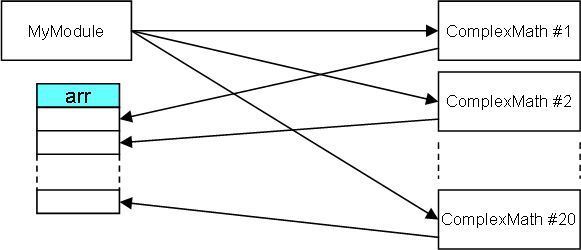
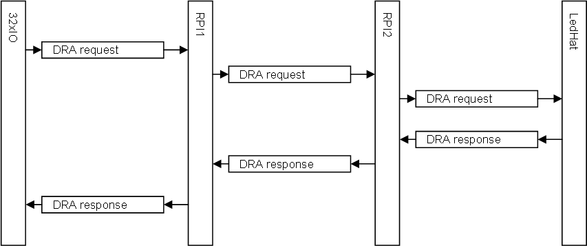
My previous example shows how I can call a function located on a different device. In this New example I want to set the leds directly from 32xIO by sharing data.

use System
use LedHat
Module 32xIO
            Transaction LedHat.leds[1]
                        LedHat.leds[1].Led1=1
            Update
End

The “leds” array is declared as interface allowing other modules to access it, so we can as well just access the array from 32xIO inside a Transaction statement. What happens is that we use DRA to connect between LedHat and 32xIO as previously explained, but we now need to (1) send a message to lock access, (2) make the changes, (3) commit changes. We get two extra messages, but less code this way. This was the easy part!

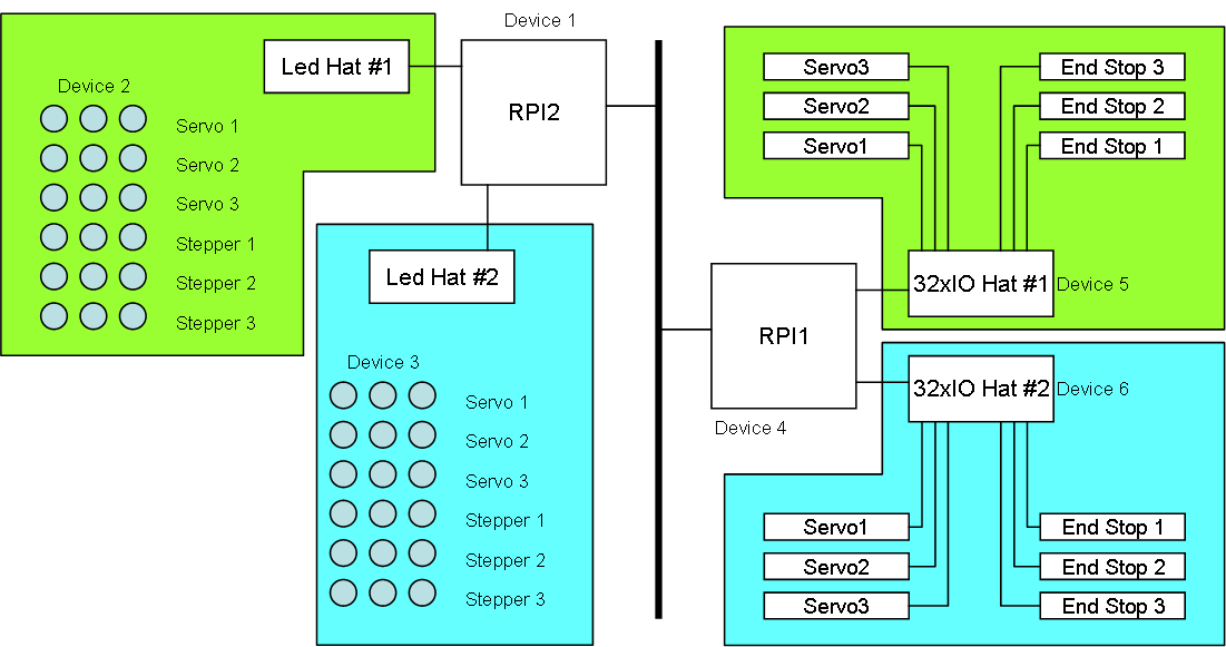
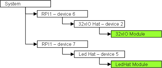
The system illustrated above is two systems wired as one just to complicate things. 32xIO #1 need to connect to LedHat #1 and 32xIO #2 need to connect to LedHat #2. This creates ambiguity as we by default will connect at random – first request will get first LedHat in list etc.

One way of solving this would be to use different module names – this is possible – but you will end up maintaining separate code for multiple devices depending on how they are used. Let’s try to avoid that as much as possible! In this case I have two “domains”, each with an array of 3 x 6 leds using the same name. And as I don’t want to hard-code the domain name I need something else.

A classic solution would be a complicated configuration, but I do not want that either – I have spent to many hours configuring complex communication systems to walk into that trap.

The concept I want to test out is a “System Diagram” – some kind off high level description of our system with modules, devices and how they connect. With this in place I would only need to tell my module what role it play in that system – lets give it a try:

use LedHat
use 32xIO
System SpiderRobot
            Domain green owner LedHat
                        LedHat greenLedGroup
                        32xIO greenIO
            End
      
            Domain blue owner LedHat
                        Ledhat blueLedGroup
                        32xIO blueIO
            End
End

The example above create a system “SpiderRobot” with two domain’s – “green” and “blue”.

I did consider using xml for this, but decided that this actually is part of our code and should use Plain syntax. I like xml because it is an excellent data storage format that can be edited manually if we need to – but, as xml syntax also can be very cryptic – difficult to read logic – this should not be part of any programming language – IMO!

pd 32xIO SpiderRobot -d blue

This is a proposed pd (program download) command. I will review the utility command line later, so this is just a quick & dirty proposal – 32xIO and SpiderRobot are plain assembly (*.pln files). -d blueIO tell the pd that the module can see domain “blue” in addition to global domain.

As the 32xIO now request a LedHat it will only be given access to the LedHat in the same domain. As we start LedHat and 32xIO we also report what domain we are, or that we are unassigned – in the later case we need to be assigned domain visibility & roles by an utility later.

use LedHat
use 32xIO
System SpiderRobot
            Domain green owner LedHat
                        LedHat greenLedGroup
                        32xIO greenIO
            End
         
            Domain blue owner LedHat
                        Ledhat blueLedGroup1
                        Ledhat blueLedGroup2
                        32xIO blueIO1
                        32xIO blueIO2
	     Wire blueIO1 to blueLedGroup1
	     Wire blueIO2 to blueLedGroup2
            End
End

This example complicate our story a bit because I decided to add a 2nd LedHat and 32xIO to domain “blue”. In this case I still do not what LedHat to connect to so we need to “wire” the system manually since auto-wiring will not work anymore.

The added “wire” statement solves this, but I just decided that having two LedHat’s was a bit much, so I want to use only one and let the two 32xIO Hat’s access different led Groups.

use LedHat
use 32xIO
System SpiderRobot
            LedHat greenLedGroup
            32xIO greenIO
            32xIO blueIO
            wire greenIO to leds[1]
            wire blueIO to leds[2] as leds[1]
End

In this case I actually don’t need domain grouping so I just specify my 3 Hat’s and how they are wired together. The wire statement only specify visibility and how we view content. The code does in this case program leds[1] so as I wire blueIO to use leds[2] I also need to specify that this is seen as leds[1].

My concern here is that we introduce too many error scenarios, and as this is a highly experimental concept we need to be open minded for better solutions or loose ends.

Raspberry PI Hat’s

I have so far designed 3 Hat’s that I have produced, and a few others in draft versions. Looking at my older picktures I seem to have uploaded 3D models, but not so many Pictures of the actual Boards – probably lost some Pictures on the old blog – I will fix that.

This is just a summary.

32 x Servo/IO

16 x Servo/IO in stacked position

STM32F105RB or STM32F103RB

Raspberry PI 2/3 + Zero

I also planned a GPIO Hat, but froze the plan because this is capable of being used for that purpose.

The 3D model is the updated Version that I have not ordered yet. The difference is mechanical changes and added protection Logic.

8 x Dc Motor + 8 x IO (end stop)

STM32F105RB or STM32F103RB

Raspberry PI 2/3 + Zero

I received the PCB’s some time ago, but have not assembled it yet. Think I finally have received all parts.


5 port Com Hat

3 x RS485

2 x CAN HS

STM32F105RB only

I have uploaded Pictures of this hat assembled, but they are on the old blog system. Build two Versions of this Board and need to do a revision due to minor mechanical issues.

I have shown 3D models of other Hat’s that still are work in progress – including some for Zero. I initially froze the Zero Hat’s because my full size Hat’s can also be used for Zero. With the new Zero W it actually is more attractive to use Zero for Wifi connection, so I might update some of my old Zero designs.

I have loads of design ideas I would like to work on, but I am a bit short of time.

Plain – Distributed Processing Part 3

The system I described in part 2 needs to send a message from a module in device #2 to a module in device #5.

This tree is basically the physical address of a resource as seen from RPI1 and RPI2. But, as this address might change with wirings we need a more generic way to program this. The key in this case is that we use the module names are a “resource”.

32xIO and LedHat are both reported as resources in the system during startup. The 32xIO module will due to the “use LedHat” statement request a “LedHat” resource and be sent an address in return. This is part of Dynamic Resource Allocation in easyIPC – a topic we have yet to cover. With an address we need to map a message routing from device#2 to device#5 – this is called a stream in easyIPC. A stream is always 2-ways.

1 The VM “32xIO” (Not the device) will initiate a DRA request. And as part of the request we assign a Stream ID on the device.
2 RPI1 decide to forward the request to RPI2 since this own a request of this type.
3 RPI2 will forward the request to the LedHat device using a managing stream id
4 The LedHat will allocate the resources and send a DRA Responce back with a selected stream ID.
5 RPI2 will set up it’s own Routing between this Stream ID’s and RPI1 and forward the response to RPI1
6 RPI1 will set up its own Routing between the stream ID’s and forward the response to 32xIO.

We have now set up a stream. Any message sent from 32xIO on that stream will be forwarded to the LedHat and wise versa.

DRA will also deal with re-allocating of resources and it is more details to it, but this illustrates how we will  (1) report the modules as resources and (2) connect resource streams in easyIPC.

to be continued in part 4 …