Hardware Abstraction Layer is a thin layer of software that “abstract” your code away from the actual electronics. Actually one of the better implementations around is the Arduino library, so it is many good reasons to copy this as much as possible. But, not all of it as Arduino was implemented on a 8 bit AVR and uses a blocking concept.
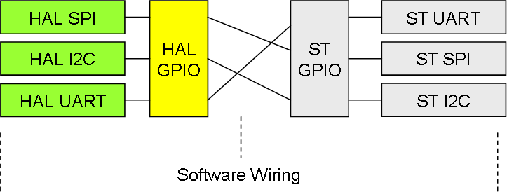
One thing we need to do different is a concept I call “Software Wiring”. As we use a HAL UART module we also need to tell the HAL module where this UART is located and what pin’s to use. ST have GPIOA, GPIOB, GPIOC etc that are physical Groups of 16 pins each, but if you access these in your code you also need to change your code if Your platform change. This reduces the portability of your source code, so I deal with this using a simple trick in the HAL GPIO module.
For each UART I create a logical HAL GPIO group that need to be wired for the HAL UART module. HAL UART will expect that Rx/TX, Send Enable, Receive Enable and Power On/Off are on selected logical pins that never will change. This Group Access physical pins through a table allowing us to re-wire in software as we initialize our platform.
The result is that I am left with a single function that needs to be re-wired to port source code from platform to platform. Obviously we also enable the physical ports 1:1 through the same mechanism.