The build in 12 bit ADC will give a resolution of 0.007V if I use it to control a 30V Lab PSU, so I was looking for something with a higher resolution. I did find something that could handle 24 bit @ 2.4Msps, but it required a NDA to see the price – I think not. A little surprised about prising on fast ADC’s.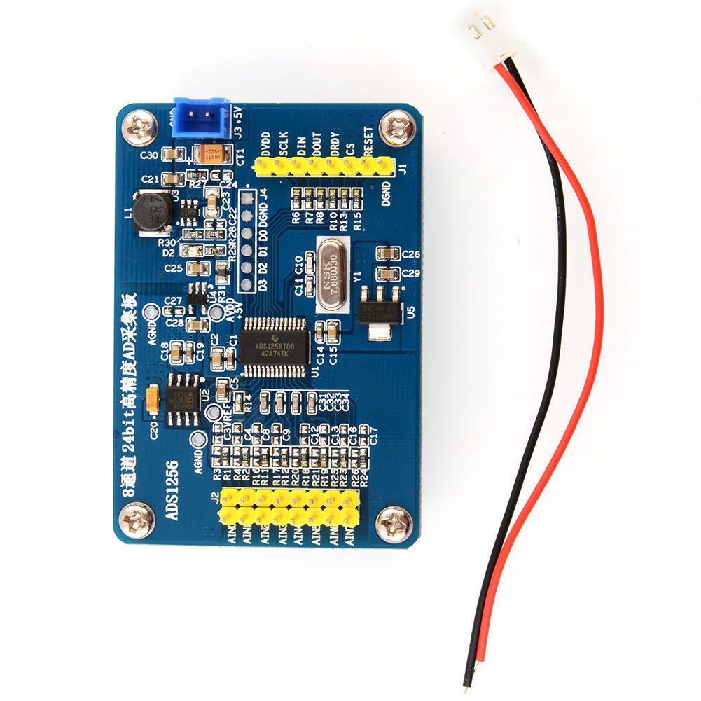
The one over is a decent choice that is quite popular. ADS1256 from TI delivers 24 bits @ 30Ksps on 8 channels for ca 6.- USD +/-. It has been around for a while. The breakout board is ca 16.- GBP on ebay. I will play with this a little, but for now I will settle with that build in 12 bit on STM32 because they are also very fast.
I do however not need fast sampling rate, I need a very fast response in the MCU on changes. The build in ADC’s have threshold interrupts that should do that for me. Fun to come.
I do however like the ADS1256 so maybe I throw up a PLC ADC board with opto isolators. Non-isolated ones exist.