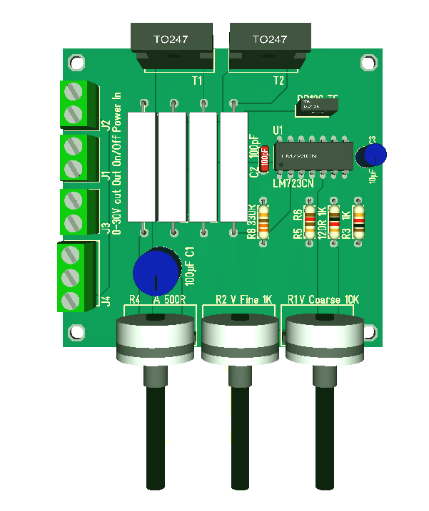
In part 1 I created an analogue linear regulator that can be used stand-alone as is. But, the drawback with a linear regulator is that it regulate by splitting voltage out between the load and the transistors. This means that if you short-cut the load you have 36V * 10A = 360W heating up the transistors. That is a lot of heat to dissipate and this is the main drawback with linear regulator techniques.
To improve on this I want to use 3 x 12V DC-DC and a few relay’s to connect in 12V, 24V or 36V as it is needed. Adding a MCU I can autosense the output voltage and if voltage out is 10V I switch in 24V etc. This means that my maximum voltage drop is 14V giving 140W to dissipate. It is much better.
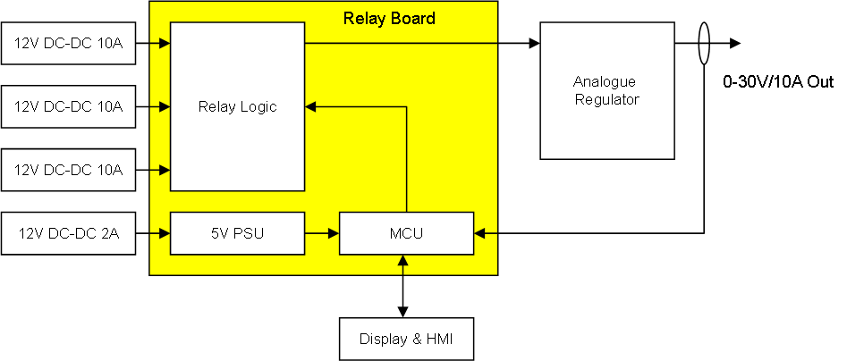
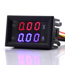
I also need a separate 5V for the MCU, Display etc, so I grab a smaller 2A DC-DC for this and add a classic 7805. By doing this I also isolate MVU power from the Lab PSU which is good. The MCU I chose is my own STM32F030 breakout board. This leaves us the option to replace this with an Arduino or whatever we want to use later – freedom of choice.
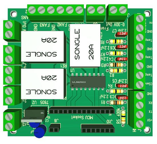
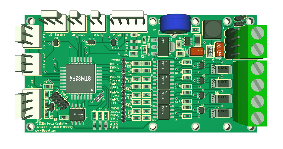
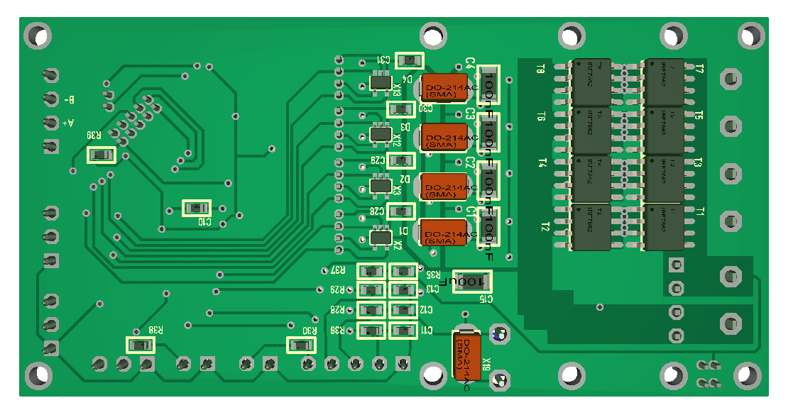
This is an early 3D model of the Relay/MCU Board- again I use hole through Technology only. The DIP14 Circuit is ULN2003. I decided to use this because the relays need ca 6V-14 to hold + having the ULN2003 between the coils and MCU adds protection.
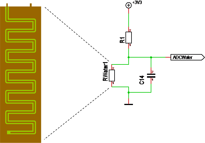
To improve our heat dissipation further we implement temperature sensors and fan’s. I have available 12V/600mA ports and ADC’s anyway so implementing 3 of these are easy. I will add schematics and BOM lists later.
to be continued…