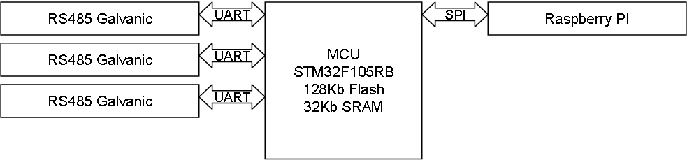
I made a 5 port (3 port RS485 and 2 port CAN) earlier that is great, but I want a version that is galvanic isolated for solutions that require wiring around a house or more hash environments. ADM2582E is a “All-In-One” package for this, so using 3 of these I get a 3-port RS485 will full isolation. This will cost ca 15.- USD more than the plain one due to the more expensive isolation chips, but those bucks are worth it.
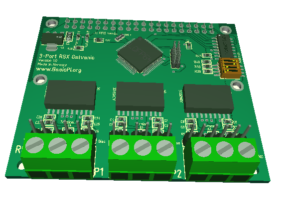
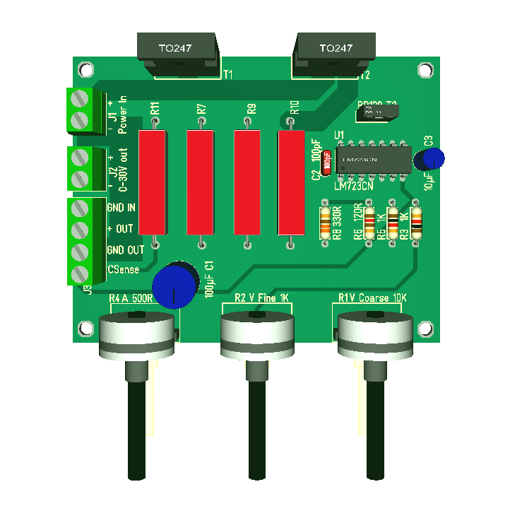
The 3D model above is a bit premature, but it gives you an idea of how the Hat will look like. I have also included a snip of the PCB to illustrate the galvanic isolation.
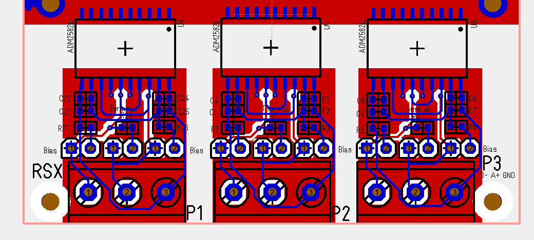
I have not connected the 3 ports to the MCU yet as I basically wanted to see if I could achieve 3 ports with proper spacing. I am actually quite happy with the result. The 4 red areas are ground. As we have isolation it means that each port have it’s own isolated ground completely separate.