PLC-/Home Automation -Control System

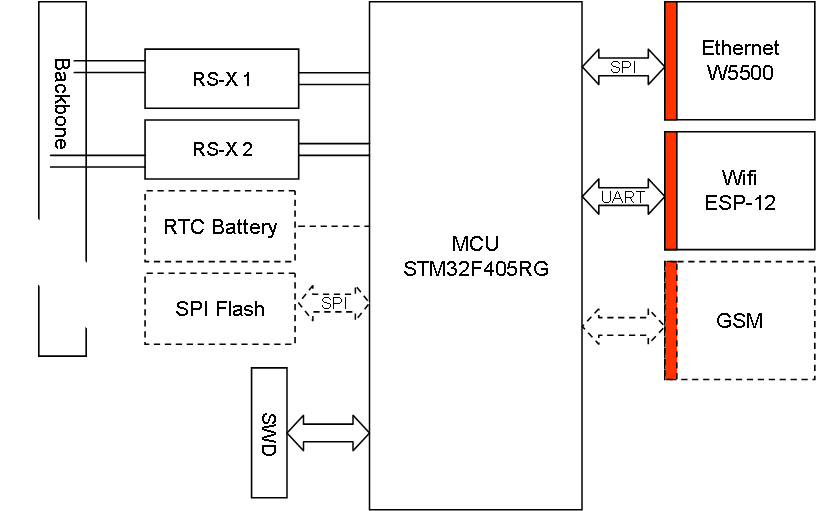
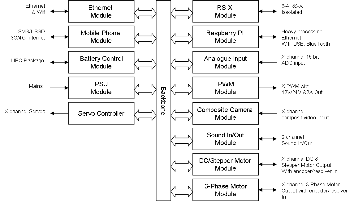
This diagram illustrate my Home Automation Centre. The idea is to use isolated RS485 networks – no power – to control actuators and sensors. Power will be entered by through RS-X adapters I will draft later. I am a bit undecided on Ethernet/Wifi as this also can be sorted through Raspberry PI. The one thing I do not like with the PI is the SD (TF) card as this is its weakest point regarding reliability. GSM is available low cost and needed for dial-up solutions. The Serial Flash act as a disk. This is only an early idea draft, so lets see where we land.

Lab PSU 0-30V / 10A – Part 6

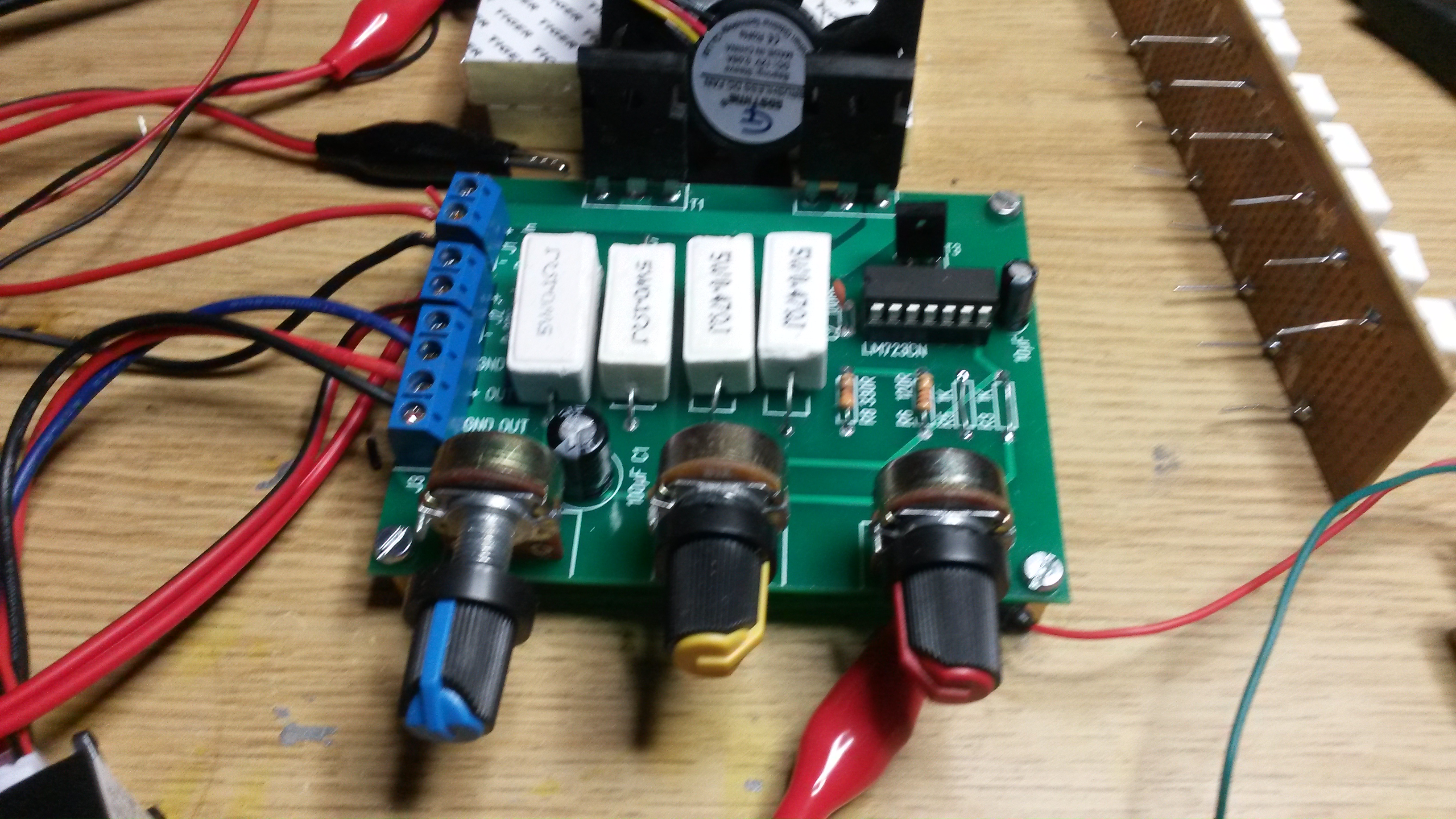
This is the schematics for the regulator side of the Lab PSU. I am using the classic LM723 in this design which allow for current and voltage adjustments through potentiometers. T1 & T2 deliver a max of 15A each, but current will be limited by the shunt resistors R14 & R7 as well as R9 & R10.

I have kept this circuit as simple as possible to give a modular, small analogue regulator. It exist plenty of doc on LM723 and example schematics on the net. I actually need to assemble this on a vero-board to verify the values I use on resistors.

What is not shown here is the capacitor board. I am recommended ca 1000uF/1A out, so I designed the cap board for 20,000uF + TVS diode. The issue with a separate capacitor board is that everyone can adapt to their own. I also realize that I might need a capacitor board between the regulator and relay board to smooth out spikes as the relays connect/disconnect. capacitors on the out path also have a second objective to protect the test equipment from it’s own nasty spikes (if it has some).

The reason for using hole through technology on this project is because it enables more hobbyists to build these themselves. I will provide access to PCB and detailed BOM lists as soon as the design is verified.

Looking forward the next step is to build one of these for verification. Part of that will be load testing and looking at ripple & noise on the output. With the regulator being a module I also have the option to use a ring trafo for a full analogue design to reduce noise if this still is an issue. The noise we talk about is PWM from the switched regulators in front. Some test equipment might be sensitive to this. I am very curious to test how good this old analogue regulator is as a end step. The classic PSU will need two of this so you can create -30V to +30V.

Distributed PLC Control Centre

Reviewing the design for a home automation system I realise that a PLC rack is not optional as a control system centre. The reason is that we will mainly be interested in central node processing and communication – we will not be interested in more classic PLC controls. Also we need these centrals to be small and hidden. I am thinking more the style of a flat packed PCB card with RS-485 ports, Wifi, GSM/3G/4G and Ethernet in a flat package with battery backup.

The diagram above illustrate the concept. We mount as many distributed centre’s as we need. These communicate with each other using secure Ethernet (wired of wireless) and control their own subnet of actuators and sensors. As these are small and can be hidden they will be easier to integrate into existing homes. Power can be various distributed mains and battery packages.

This an old picture of my universal adapter that basically can be used as is except that it lack GSM option + I would like to have an option to Connect Raspberry PI (3 or Zero W).

Lab PSU 0-30V / 10A – Part 5

As we log output voltage, current as well as few other things it would be nice to be able to display a real-time oscilloscope alike picture of these. This functionality is only available on PSU’s far more expensive, but is easy to achieve thanks to the Nextion displays. The illustration below is a draft of the front panel.

This is a draft of the internal layout. I have not added the cheap voltage/current display here, but that can be added as a replacement or addition to the Nextion display. Nextion 2.8″ cost ca 19.- USD.

What is left now is the waiting for PCB and parts so we can assemble this. That will take ca 6 weeks, meaning that I have to august to write the firmware for the MCU and HMI. All in all I ended up with a ca 100.- USD PSU with very advanced functionality so it will be exiting to see it working.

to be continued …

Lab PSU 0-30V / 10A – Part 4

This metal box is not exactly the prettiest Project Box I have seen, but it cost 17.- USD including P&P and measure 250x190x110mm. I ordered one for testing because the more fancy alternatives cost closer to 100.- USD.

What we now miss is the mains adapter with fuse, which is a 3.- USD component. We wire this to an On/Off button in front before we connect to the DC-DC connectors that again is connected to our Relay board that again is connected to our regulator board that again is connected to our capacitor board. Myself I have plenty of 12V/10A DC-DC converters available, but you can find these for ca 10-15.- USD each. So 17.- for the box, 3 x 15 for DC converters, ca 10.- for each board + some extras leaves us at < 90.- USD so far. For a 10A Lab PSU we could probably as well have bought one for this price, except for the next detail that makes it all worth it – the HMI.

to be continued…

Lab PSU 0-30V / 10A – Part 3

I did not add much capacitors on any of the boards simply because they take to much space + I wanted a separate capacitor board to be able to scale up/Down and be more flexible about mounting them due to their size.. I found some very nice sized 10,000uF/50V that I am using that have a decent size to them. We need to add one of these on the out step (before the out relay) to make the PSU capable of dealing with nasty behaviour from test equipment. I also wonder if I might need some caps between the relay board and the regulator to smooth input voltage changes – will see.

The TVS diode should clamp down on ca 45V to protect the 50V capacitors in case we deal with spikes caused by 360W of fun.

What I will do next is to review the full PSU and adjust for assembling of the entire PSU. That include looking into a project box and HMI solution.

to be continued …

Lab PSU 0-30V / 10A – Part 2

In part 1 I created an analogue linear regulator that can be used stand-alone as is. But, the drawback with a linear regulator is that it regulate by splitting voltage out between the load and the transistors. This means that if you short-cut the load you have 36V * 10A = 360W heating up the transistors. That is a lot of heat to dissipate and this is the main drawback with linear regulator techniques.

To improve on this I want to use 3 x 12V DC-DC and a few relay’s to connect in 12V, 24V or 36V as it is needed. Adding a MCU I can autosense the output voltage and if voltage out is 10V I switch in 24V etc. This means that my maximum voltage drop is 14V giving 140W to dissipate. It is much better.

I also need a separate 5V for the MCU, Display etc, so I grab a smaller 2A DC-DC for this and add a classic 7805. By doing this I also isolate MVU power from the Lab PSU which is good. The MCU I chose is my own STM32F030 breakout board. This leaves us the option to replace this with an Arduino or whatever we want to use later – freedom of choice.

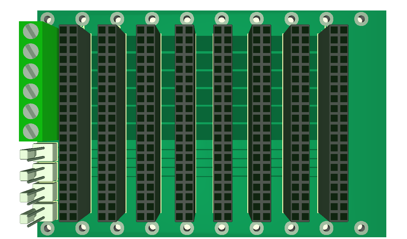
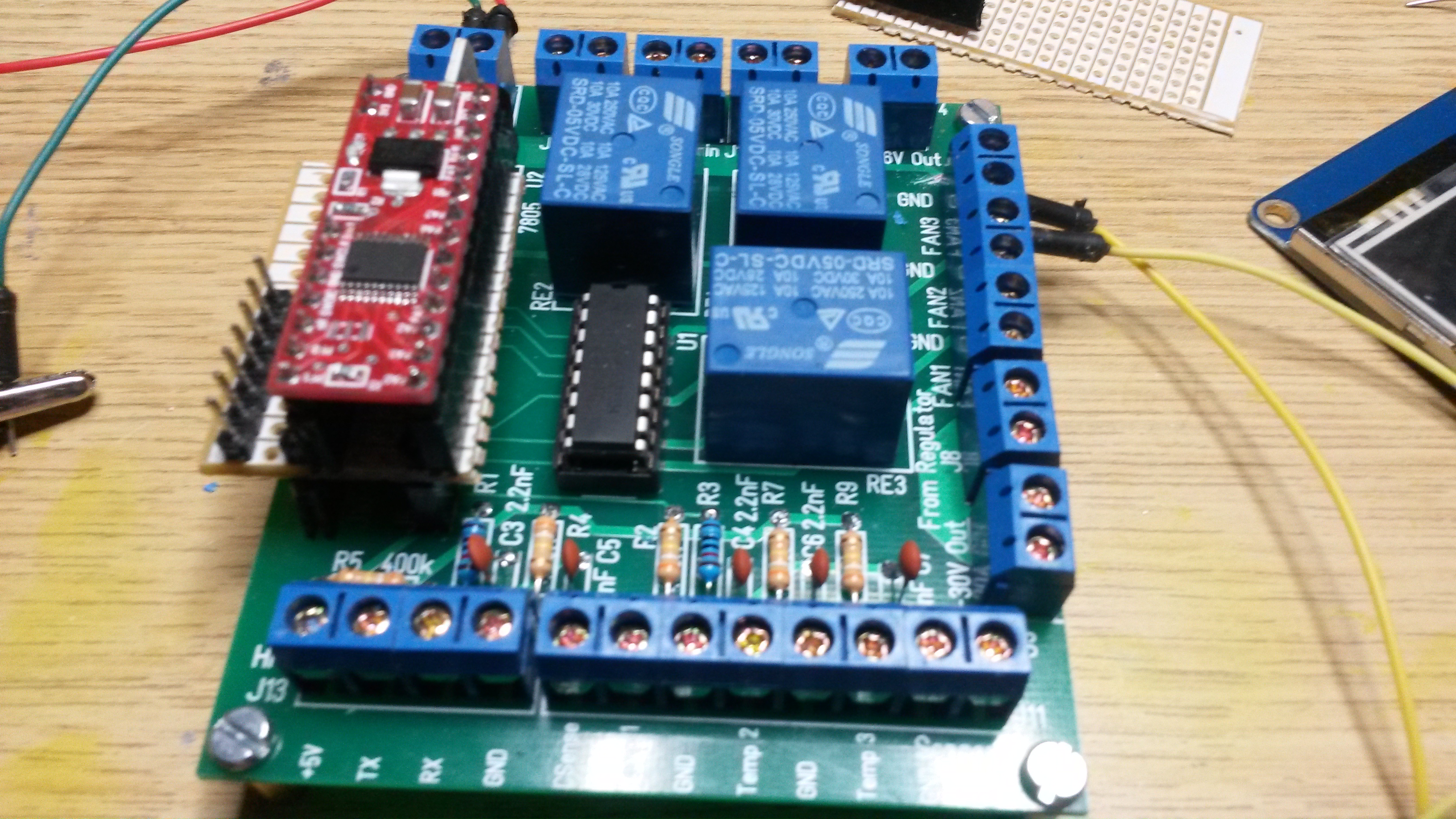
This is an early 3D model of the Relay/MCU Board- again I use hole through Technology only. The DIP14 Circuit is ULN2003. I decided to use this because the relays need ca 6V-14 to hold + having the ULN2003 between the coils and MCU adds protection.

To improve our heat dissipation further we implement temperature sensors and fan’s. I have available 12V/600mA ports and ADC’s anyway so implementing 3 of these are easy. I will add schematics and BOM lists later.

to be continued…

Lab PSU 0-30V / 10A – Part 1

I desperately need more lab PSU’s and I have a bunch of LM723 and TIP3055 transistors that are excellent for creating an old-fashioned Linear PSU module. Thinking a bit ahead I want to create the analogue regulator as a small, separate module with knobs on the front, heat-sink & transistors on the back and connectors on the side.

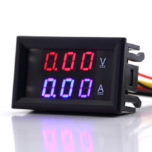
The 3D model above is an early draft on 70 x 75mm. I am using hole througt Components on this one to enable hobbyists to grab a PCB and solder them up themselves to save cost. Adding a Voltage/Ampere meter is easy because I just use a module like this one (or similar):

They cost less than 5.- USD and they work well. I add no other led’s or display, but I add two power switches – one for input and one separate for output.

I am also using 2 x TIP3055 that technically enable 30A together, but PCB lanes and current limit is scaled for max 10A. The following block diagram show the complete PSU.

The mains are basically a 36V/10A DC-DC regulator. These comes at a decent cost with CE/FCC approval that is needed for 48V and higher. What is remaining is to find a project box and we have a nice Lab PSU.

to be continued…

Water Detector

This drawing illustrate a water detector. A water detector is basically a standard ADC reading between two resistors where the 2nd resistor is a PCB as illustrated above. As the water raises the PCB will start leading current and the ADC reading will move from 3.3V to GND. This is the same principle as used for temperature- and light detection resistors- except that the resister is a PCB in this case. We we can apply the sensor with a cable some meters from the actual sensor Logic as we don’t want electronics flooded.

A water detector is something you don’t believe you will need, but if you ever have a water leak you would like to know about it fast since water usually cause less damage if it removed instantly.