Ethernet Module

Just an early 3D model of the Ethernet Module including Ethernet, Wifi and GSM based network connections. I have to add the 3D modules of the sim card holder and antenna that also goes to the front, but I am running out of space. These modules are only 80 x 65mm, but that is in my opinion needed for mobile PLC’s.

Plain – hitting the road

I wrote lengthy blogs about Plain syntax and concepts earlier this year and want to wrap up the specifications and get going. The challenge with pushing on ideas and concepts is that you start getting blind-folded and stuck as you push for results. This is why I prefer new concepts to mature because what seems like a good idea one day might not the second day. Many of the concepts in Plain have however evolved over several years as I started on this far earlier than this blog.

The difference with other programming concepts is that I don’t want to create another language, I want to evolve the way we work so we can achieve more with less. Plain embrace several new concepts aiming for that, but this is untested theory. I believe it will work as expected, but I am also prepared for setbacks as we move forward.

Plain is also more difficult to achieve than normal programming languages because I need electronic devices supporting it and an established infrastructure to build on. Things take time, but we will get there.

Thanks for reading.

3.3V 5V, 12V or 15V Switched PSU

This is the PCB for my switched PSU. It takes 40V in and can be made to produce 3.3V, 5V, 12V, 15V etc. With Pictures you loose a bit feeling of the actual size, so I put a TO247 transistor next to it – this is the smallest PCB I have made so far.

It is designed as a drop in replacement for linear regulators since I often need 2-4 PSU’s on a motor/PWM design. Regulating from 40V to 3.3V means you use a lot of Power. Will assmble a few of this for testing later.

PLC – 24-bit Analogue Input Module

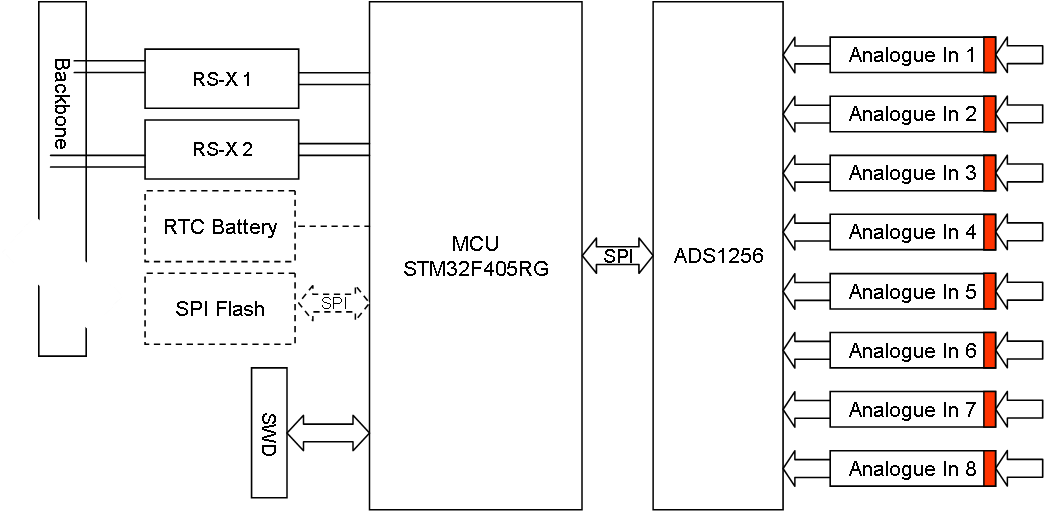
This analogue input module uses a ADS1256 that allow 8 channel input with 24 bit precision and 30Kbps sampling rate. With a programmable gain amplifier 1:64, programmable filter and support for single or differential inputs as well as calibration this board can cover most ADC needs.

The input here can be 8 stand-alone channels or 4 differential channels. A stand-alone channel will measure voltage between input and ground, while a differential channel measure voltage between two points. The later is more flexible as it also can be used for current loops. The challenge is however that different usage require different line adaption circuitry, meaning we will need different analogue boards.

My primary focus is on typical analogue sensors like light, temperature etc. This example circuitry feed a voltage in that is split over 2 resistors with the sensor being the 2nd, variable resistor that changes with light, temperature etc. A typical ADC line driver is shown below:

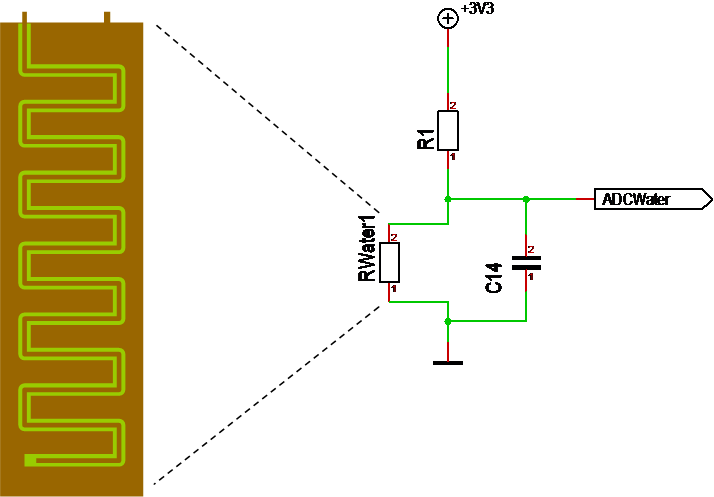
This is the water sensor I illustrated earlier where we use a specialised PCB as a resistor. R1 need to scale the input so we get 0-3.3V out to the ADC. The capacitor is only a filter. More important is that we can Interface to this in two ways – we can create a 2 pin connector for the external resistor only, or we can supply +/- and expect an analogue value in. Many modern sensors will require the last 3 wire Interface as they provide their own specialised analogue interface.

The main drawback with this technique is that we can only have a limited distance between sensor and the ADC since the wire will start acting as a resistor that needs to be taken into account. A different analogue technique that can be used over 5km is a current loop – I will consider making a Board for that later. But, also remember that we have RS-X based sensors that can cover some distance in wiring.

PLC – Raspberry PI Module

This illustrate the Raspberry PI connectivity board. The PSU on top can be switched on/off so we can reboot RPI. The actual RPI will connect using a 40 pin Connector. I am not sure about the mechanics yet, but I am considering mounting it so it’s Ethernet and USB sticks out in front. The adapter board will as far as RPI goes be a Hat using Smart SPI. Basically a Hat with a 40 pin for backbone + the standard PI 40 pin. This Hat should have fixed address 0 and optionally be able to use a higher speed on the SPI.

Expected usage of this is that we use this for cryptic internet access, to provide web servers, complex HMI or simply heavy math. A M4 is fast, but it is no comparison with it’s a Quad 64-bit 1Ghz bigger ARM Brother. I am also considering phone and Speech services that require this grade of Computing Power. It is a lot of Things that is much easier to do on a PI than on an embedded computer.

PLC – GSM Module

This is a draft of the the stand-alone GSM Module designed around the SIM800C module. I still want to see if I can get this into the Ethernet module, but made the diagram above to illustrate the content.

The primary interface to the MCU is UART + some GPIO. This uses the AT command set to control the GSM.

An USB is available from the GSM Module for debug and firmware download. The intention is to connect this to the USB on the MCU as well as making it available through an extern port. I have a loose end on how to do this that I need to dig into. I might also put this port a bit hidden as it is only optionally needed.

GSM antenna need to be added.

SIM Card holder need to be added.

Sound In/Out is usually to a mic/speaker. As this is not a phone, but a PLC we would like that digitalised so we can play sound files, do funny things like speech recognition etc. The later will require a Raspberry PI (Zero ) Add-on to do the processing. I am thinking of running an open source solution where the GSM act as a line card to FreeSWITCH or Asterisk + PocketSphinx to support a single line.

All in all I must admit that this module will require some space, so it might be a bit crowded to get in on the Ethernet Module – lets see. It’s a lot of loose ends here yet.

PLC – GSM – SIM800C

Looking at SIMCom support for the SIM800C I must admit that they impress. I had to register on their site and after that I have Access to 20 Application documents, AT commands, certification documentation and updated hardware design & user manual.

I have a dev-kit on it’s way + a module, also a devkit of the SIM800L.

This is the smallest of the modules I am looking at measuring only 17.6 x 15.7 mm. The hardware design guide is well documented With schematic examples and With 20 app notes that seems to have decent complexity and content this will be fun.

What I need now is antenna and SIM card holders etc for my Ethernet module. How I use the GSM is still an open question – it has a TCP/UDP Interface, but I wonder if SMS Messages are more cost optional – or maybe a mix.

PLC – RS-X Module

This board enable 3-4 RS-X networks with full isolation. We connect 2 x RS-X to the backbone and 3-4 (a total of 5-6 UART) to external networks. In addition I want to add RTC and SPI Flash if I have pins & space. The red box on RS-X Ex mark that these are galvanic isolated networks.