Ethernet/GPRS Module 3D draft

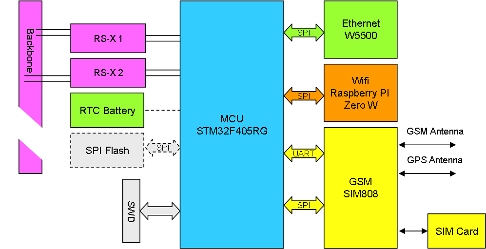
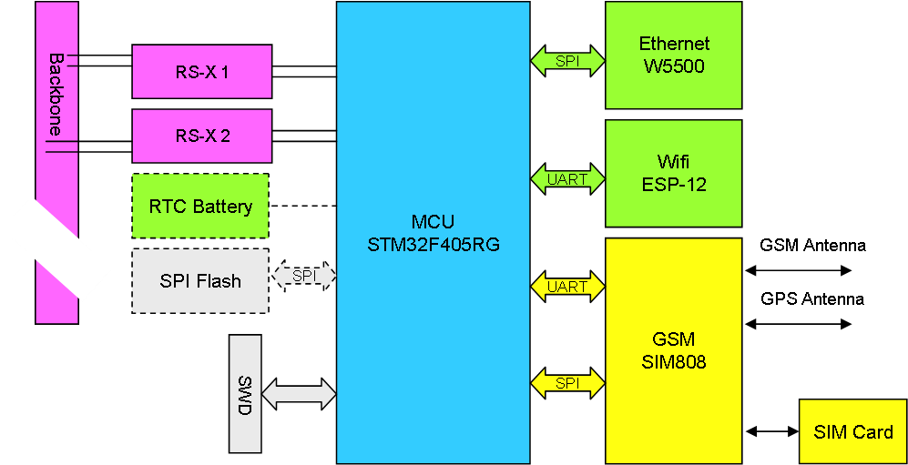
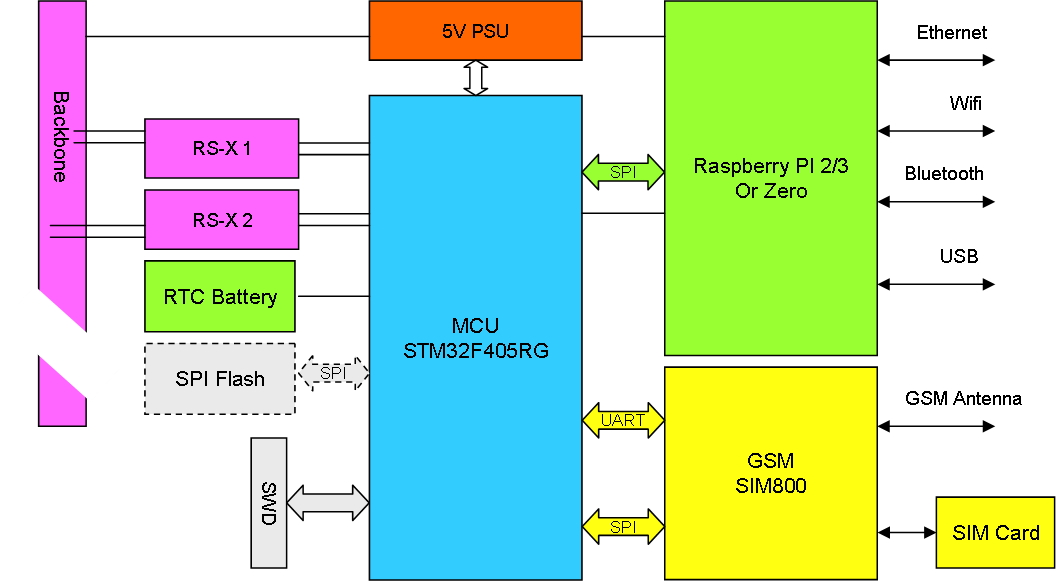
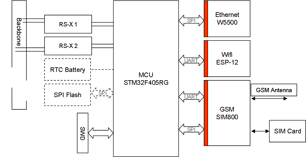
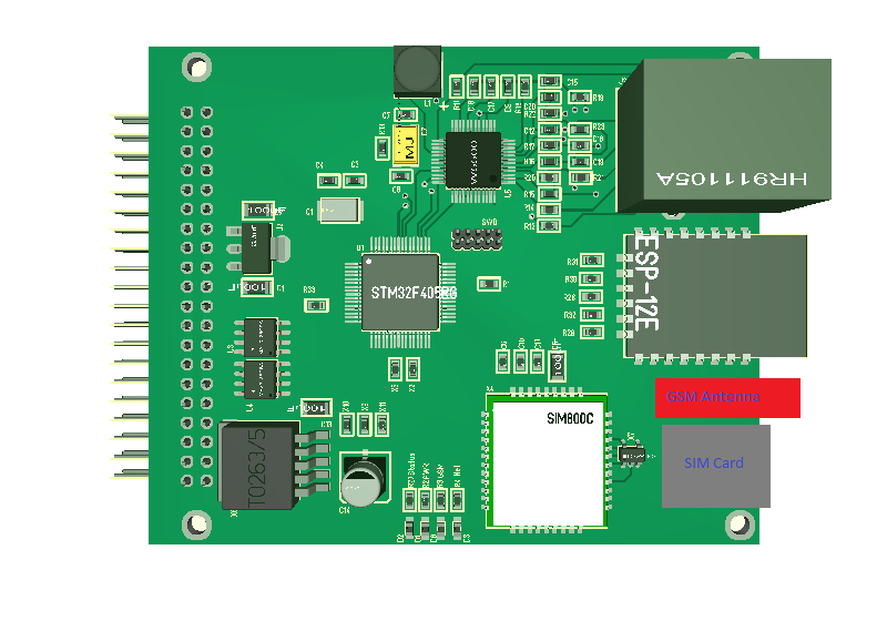
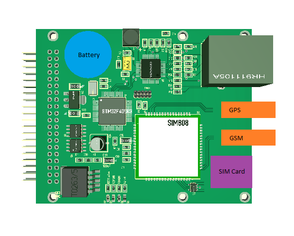
Meet my new Ethernet/GPRS module. I am not finished routing the PCB and lack some 3D packages, but you get the idea. This 3D modeling tool is a bit ruff in the edges anyway, but it serves it purpose. Also, I still have a few loose ends here – so work in progress…

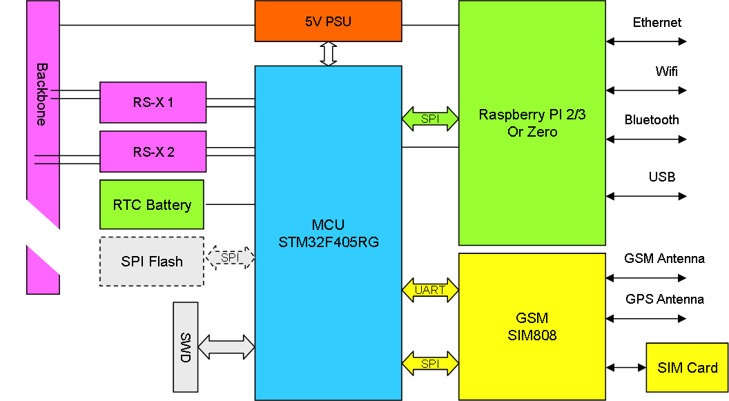
This 3D show a small button battery holder for RTC, but the SIM808 has a build in battery charger for a single 3.7V LIPO so considering if I can use that or add my own – I consider attaching a larger 3.7V LIPO battery on the back side to drive both MCU and SIM808, but I also need on/off for RPI if I do that. Basically the 5V from the back plane would charge the battery. For RTC I could use my old trick an insert a small supercap.

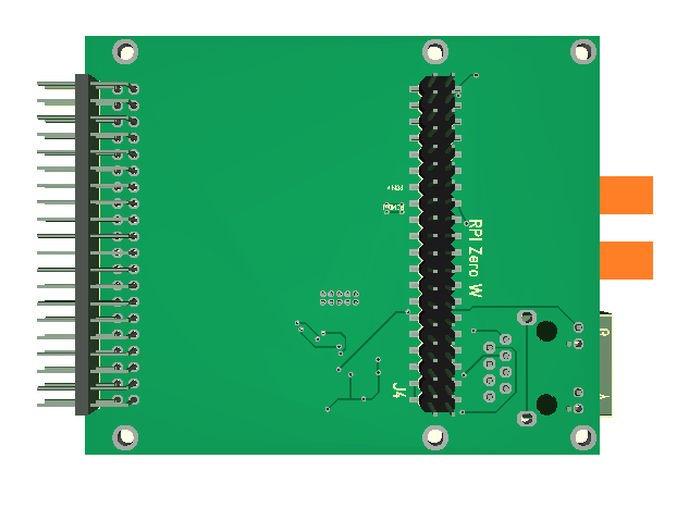
This shows the backside with the connector and mounting holes for a Raspberry PI Zero Wireless add-on. This add’s secure wifo + bluetooth as well as a very capable Linux server. HDMI & USB will be at front. Needless to say this can also connect a full Raspberry PI 3 using a 40 pin cable.

I am considering using the Space left of the Raspberry PI module for a LIPO battery as mentioned earlier.

As for the All-In-One Home Central I could just make a 1-2 card dedicated backbone with a 5-6V adapter and this would serve the purpose…

At precent I see no purpose in makeing a separate GSM, Ethernet or RPI module as indicated earlier – this combi does the job very well. Don’t be surpriced if you see the Zero W popping up as an option on more modules.

Loose ends/notes:

  • Battery charger/LIPO- I have little Insight into the build-in charger, so consider finding a different solution that also can be used on other Boards. Need digital on/off for RPI.
  • Antenna – not sure about the quality of my PCB shielding so considering using these micro taps and allow people to supply a shielded cable directly rather than adding 3-4cm of PCB lanes.
  • USB. I have space to output pins, but not for a connector.
  • Mic/Speaker – I have space to output pins to a header.
  • Bluetooth antenna on SIM808. Should try to add a micro antenna connector – yet another component I need package for. Not sure I ever need this, but I do have space for it, so why not.
  • GPS antenna crossing RPI header. Should ground pin 15 (GPIO22) & 16 (GPIO23) on the RPI header to create a continious ground plane under the antenna signal.
  • GSM Antenna is close to the SIM card. Possible to just move the card holder to the otherside with strong ground plane support to minimize effect. Either that or moving the SIM card holder to the middle of the card in which case it will be a pane to insert card. Not sure if this is a big issue.
  • RTC oscillator must be added, but little space here. We can use the HSE/8, but not sure how accurate that option is. Possible we can ignore the RTC clock on STM32 as we also have one on SIM808.
  • Consider if we need to add TVS on 4V. The Reference recommend this due to 2A on/off surge. This should not be any issue with a LIPO connected here. But, we should have space for this TVS so could just add it on PCB.
  • Some other LEDS from SIM808 – not sure if they add any value.
  • Top/Bottom edges need a clean up. Considering using a sliding holder and avoid screws in which case we need 1-2 mm clearing on top/bottom for a track.
  • Need to increase aura around drill holes and avoid these being ground. This is a mistake I have done repeatedly as I by old habit ground through mounting holes.
  • Need to adjust mounting holes for Raspberry PI Zero accurate.

PCM Interface – I2S

PCM Interface is a kind of standard build on the same principles as SPI. The SPI interface can handle the clocked bit-streams, but I2S can also handle the PCM encoding. In simple words I should be able to send/receive voice effortless – just need to get my head around register settings in STM32F405 which is made easier with STM32CubeMX (see Picture) – just a few clicks and you have sample code to play with. Just watch out because not all options are available in CubeMX.

Not sure if this is the correct setting – the PCM_CLK from SIM808 is fixed to 256Khz which is twice the frequency I need for 8000 Hz which is telecom standard (8000 * 16 = 128000) – assuming 1Hz on the clk is 1 bit I am missing something…

This is the issue dealing with various Chinese components – documentation in English is often limited – but we will sort it out.

The M4 is basically so fast that I was prepared to do this protocol the hard way – first time I look into the I2S and how it’s used. We have 2 of these available.

Ethernet/GSM/GPS/RPI Module

I decided to replace ESP-12 with a Raspberry PI Zero W fitted on the back facing front. The PLC card is of the same height as the PI Zero Length, so this is perfect. Mountimng it on top was difficult due to the Ethernet connector sticking out +  I had no space fr routing. I had to use a SMD version of a 2.54 pin header, but that’s fine. One of the things that made my decition is lack of encryption on ESP-12, something a Zero W does easily and you get a full Linux server as a add-on for 10.- USD.

The SPI Flash is still shown as an option, but I have no 4th SPI port so this is in reality ditched. I do however have an annoying right top corner with nothing – perfect for a RTC battery. I am in the process of routing this PCB and we are still at 80 x 65 mm. It will still take me a few days before this module is done.

SIM808 GSM, GPRS + GPS

Choosing GSM modules is a pain, but I landed on SIM800/SIM808. The difference is that the later contains GPS for an additional 4.- USD. I was first tempted to save those, but decided that a GPS add a very nice function for anything that is mobile. At a price of ca 10.- USD this is still affordable – so here we go – updated draft of the Ethernet module above and the RPI module below.  The only reason to chose SIM800 would be price, but I actually expect these prices to drop.

As mentioned earlier the RPI version will be a Hat that also plugs into the PLC backbone. I will work on the layout details – RPI is a bit tricky as it has connectors on 3 edges.

The reason I want both these are because I want an alternative that don’t include a Raspberry PI due to size, cost, slow start-up and SD-card (in)reliability. I am not blind for the option to combine these two into one – making Raspberry PI an optional add-on module.

SIM800 & SIM808 GSM Modules

I initially wanted SIM800C because it support voice calls and it does analogue voice. My first idea was to connect this to a ADC/DAC on the MCU for digital voice services, but this is a bit complicated and involve a digital to analogue to digital conversion that I would avoid. What I need is “digital audio” support or more correctly PCM.

PCM is a “linear” version of the a-law/u-law used in telecommunication. The interface is 16 bit and uses a sampling rate of 8000Hz that is standard in legacy phone systems. SIM800 & SIM808 are two of the modules that offer a separate PCM interface as a bit-bang protocol.. The PCM interface on both modules can probably drive a SPI in Slave mode directly (not sure). The main difference seems to be that SIM808 include GPS.

Both these modules are a bit larger than SIM800C, but they offer a much nicer path to sound support from the MCU.

Ethernet/GSM Module

I can use my Universal Communication Adapter to code most of what is on this card, so I am in no hurry to order this PCB. The fact is I miss package sizes, so I just need to sit & wait a little for now. I am however running out of space in front, so I am considering increasing the size from 65mm to 75 or even larger. I am going to draft some of the other PCB’s to make up my mind.

I dropped sound support on this and I am a bit disappointed with the need for a 4V/2A PSU that require some extra space. This makes the GSM module much larger than you expect it to be. One nice thing about this PSU is however the digital on/off pin enabling me to switch off GSM power completely. I am drafting with SIM800C to get experience, but I have not decided what module to use yet. It is sometimes very difficult to choose without experience so you see what the differences mean.

I selected SIM800C over M590E due to sound support, but as I realize that sound is analogue only I need to look into the other (and maybe far more expensive) modules for digital sound support. The issue here is that using am ADC/DAC is possible, but as the sound is digital inside the GSM module I would rather swap to a module that offer sound IO on digital packets to avoid the extra noise. I need to work on this a little – nothing is settled yet.

I am also considering moving the GSM module to the top to let the antenna be on “top”. to avoid that it is in the way of Ethernet/Wifi.

Also, the difference between this and the All-In-One Home Central is very small at present…

PWM Module 8×12-48V/3A

This draft illustrate a PWM module based on the driver of the motor controller we made earlier. We use a concept of a gate driver and 2 x HEXFET to create a Half H-Bridge. We will need 10V+ due to the gate driver, but we only need 1-3A on this one. I think it is realistic to have 8 channels, but if not we will reduce the numbers. PWM out will be anything from constant voltage to 0 duty. We will pulse on/off and use a 2nd frequency to pulse (regulate voltage) within the main pulse.

This targets solenoids with 12-48V and <3A.