Just checked my blog statistics. Last year was an average of 112 lookups per day at 1min ++. Last month was 192 per day at an average of 2 min per reader.
Thanks for reading!
Just checked my blog statistics. Last year was an average of 112 lookups per day at 1min ++. Last month was 192 per day at an average of 2 min per reader.
Thanks for reading!
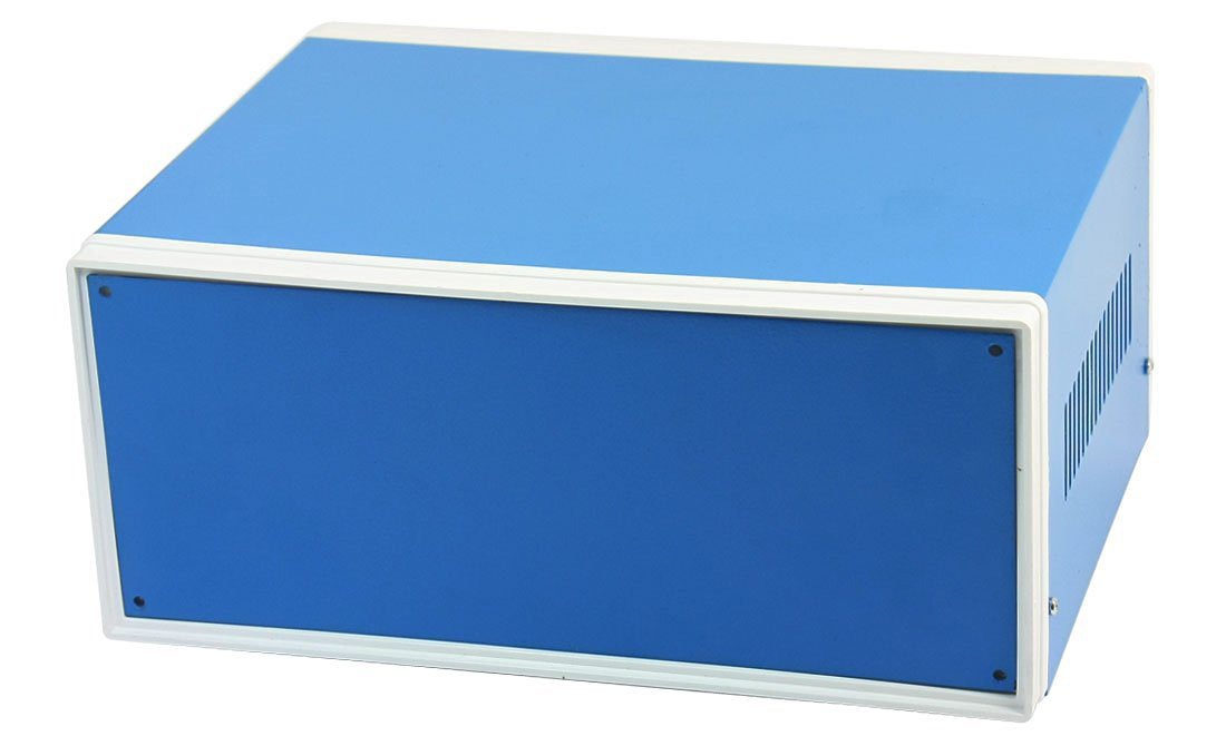
This aluminium box cost ca 16.- USD P&P included and is accidentally the correct size to mount 2 of my backbone PCB’s on the inside. I need to do a more exact scaling, but the concept is illustrated below.
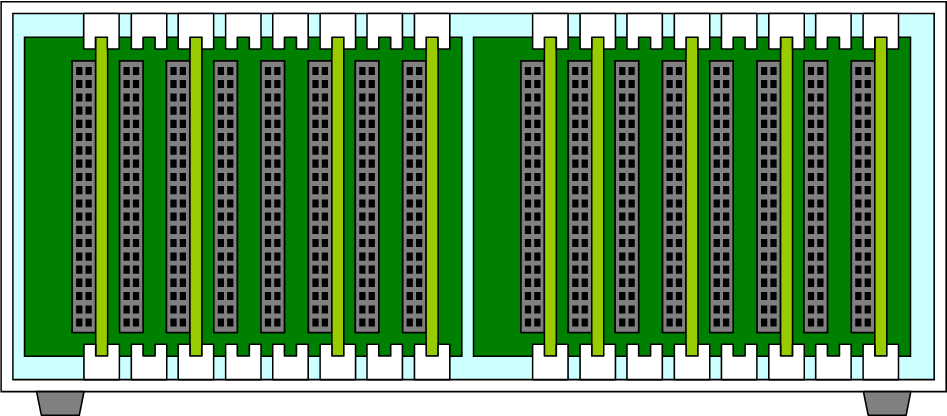
To do this I need to make some PCB Holders. The ones illustrated below should be easy to pring with a 3D printer.
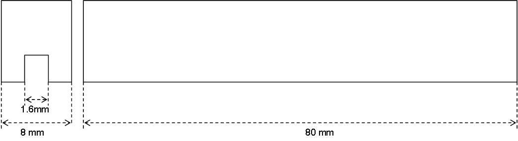
The Box have sufficient depth to hide a PSU behind the backbone to deal with mains input. Just an idea
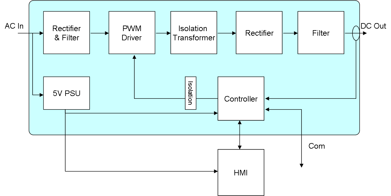
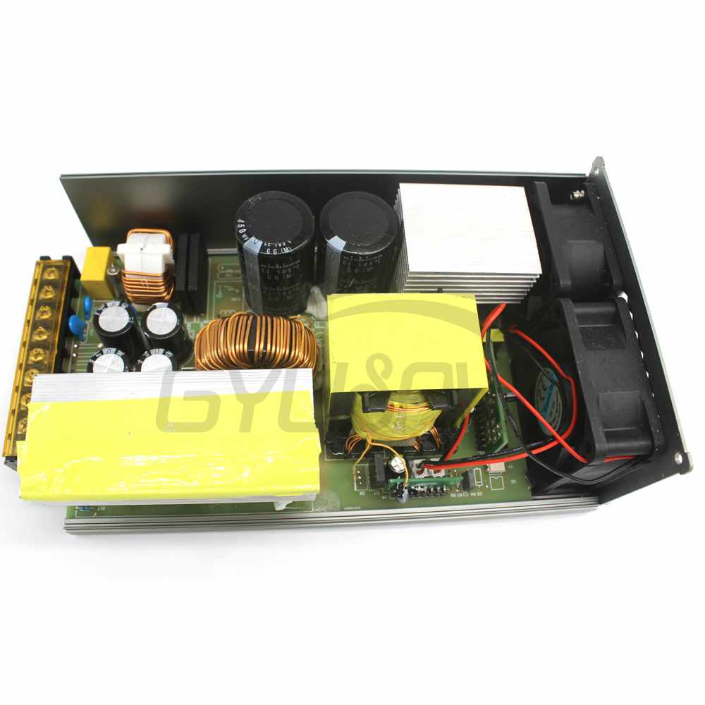
Starting at left with 230VAC input we need a classic rectifier and filter that will produce high voltage DC out. This is input to a PWM driver that will use HEXFET’s to generate a MCU controlled PWM into the isolation transformer. The duty of the PWM decides the output voltage. If we have 400VDC and a duty cycle of 10% we will have 40VDC in average out. The 2nd rectifier ensure we got all positive voltage out and the end Filter (illustrated below) convert this to a stable DC out. To Control this we use fast ADC’s to read output voltage and current into the MCU that control PWM duty.
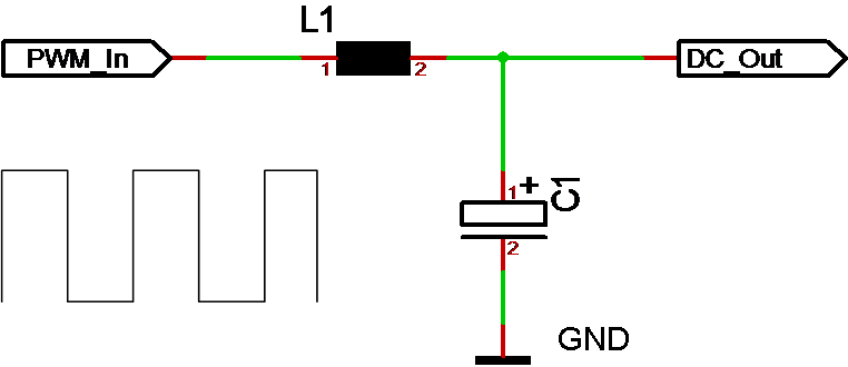
The core of any PWM driven PSU is the prinsiple that we provide a PWM in where an output filter consisting of a coil and capacitor force this back to a stable DC. Voltage out is a simple average calculation, meaning that we control voltage with setting PWM duty.
I ordered a DPS5020 (50v/20A) Lab PSU for 45.- USD with USB connector. I intend to hack that serial port and extend the HMI with my own interface, but my primary challenge is finding an affordable AC/DC that will deliver 60V/20A as input. I did find some interesting alternatives:
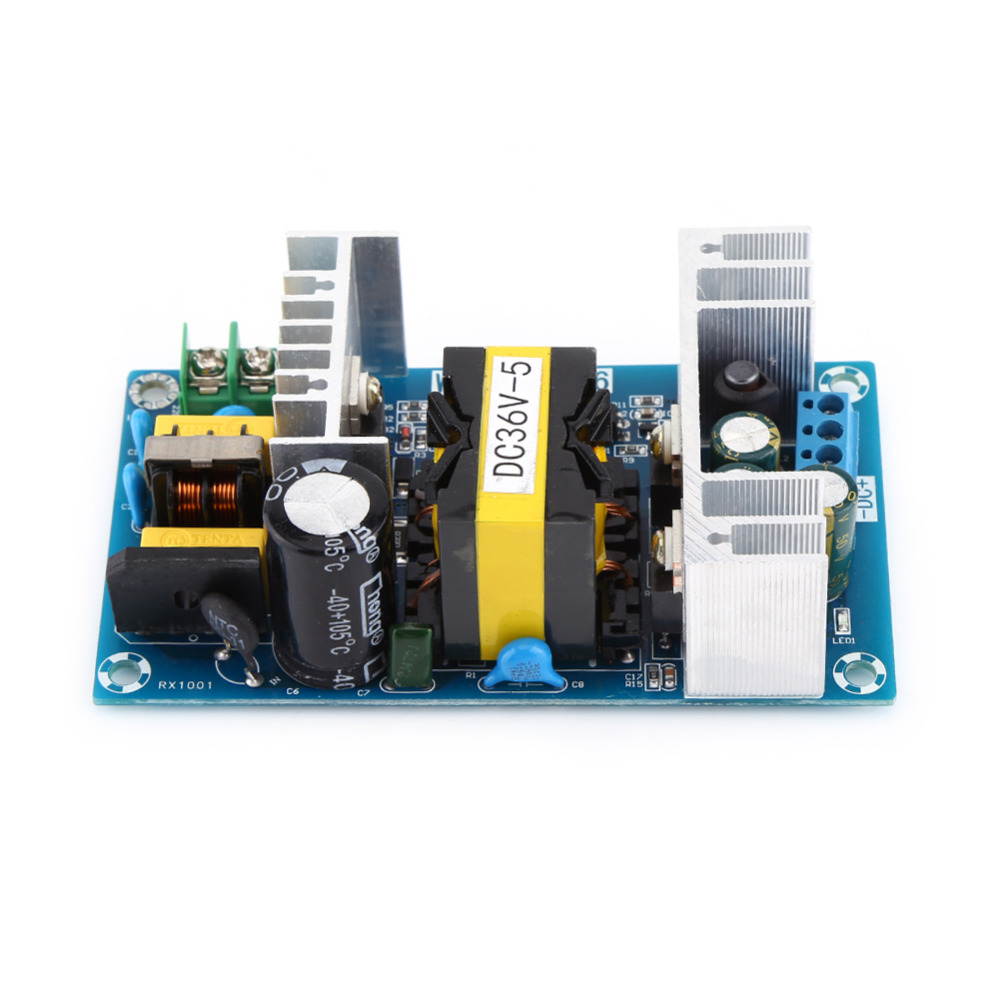
This is 36V/5A and well suited as input stage for a 0-30A/0-5A Lab PSU. It is also quite small. I ordered one of these because it only cost ca 11.- USD P&P included. A 20A PSU is a monster needed for motors, but a 0-30V/0-5A is a “bread & butter” PSU that you need several off.
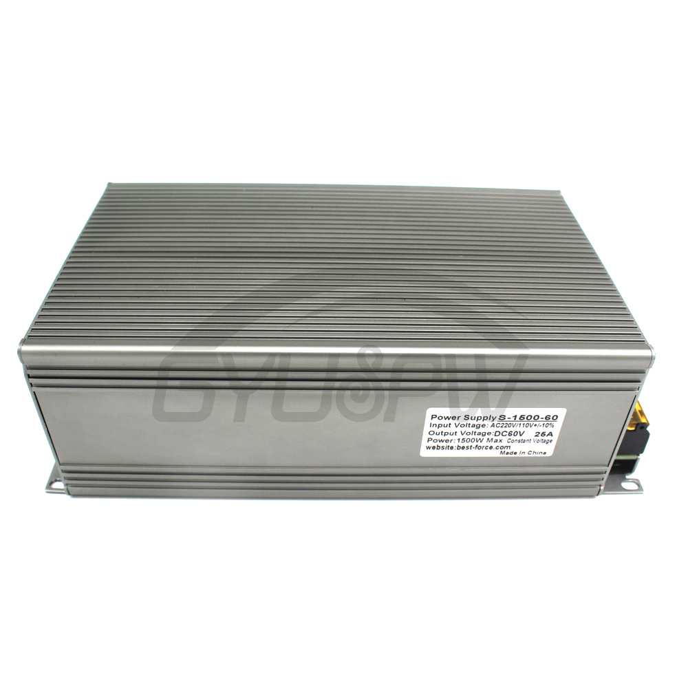
The best priced single 60V/20A unit I found is this that actually is 25A at 124.- USD. You have to be aware that both voltage and current will drive prices a bit, but as I know that higher currents are the worst to deal with I looked for 60V/10A units and found the one below.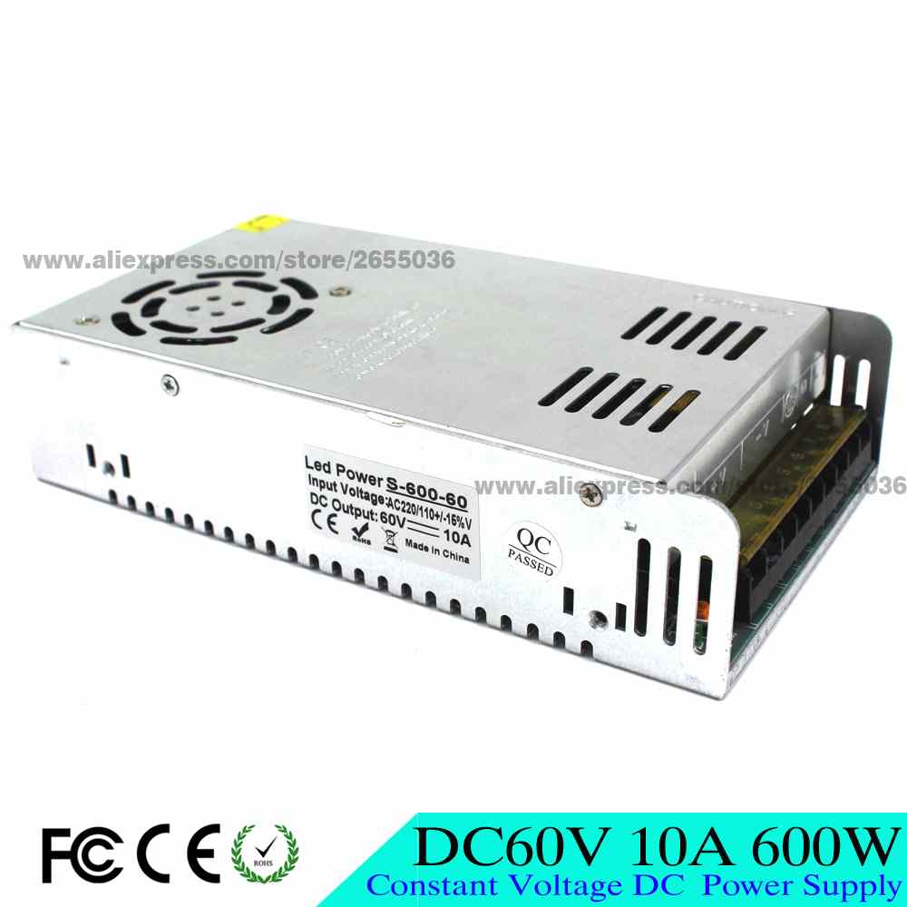
This cost ca 30.- USD if you order 10 units so I need to think about that. You can also buy them single units for ca 36.- USD. To achieve 20A I would need 2 of these that require some size, but the advantage is that I make 20A wires myself which makes each driver PSU cheaper. This gives me a cost of a driver stage around 70.- ++ USD which is decent.
Getting a box for the largest 50V/20A Lab PSU will cost around 100.- USD sadly. Adding 70.- for a driver stage and 45.- for the module + an estimated 30.- for extra bits I will land on ca 245.- USD for a 0-50V/0-20A Lab PSU.
The “bread & butter” 0-30V/0-5A Lab PSU is easier. We can pack 2 modules into the 16.- USD Blue box I showed you before and with 2 x 30.- + 2×10 and some 20.- in extra parts we should have a small, dual PSU for ca 116.- USD (of ca 58.- USD each).
Both those are decent options taken into account what the spec of these PSU’s will be – that said I want to receive the units and do some testing before I invest more time and Money on this.
The next module I want to make is the Servo Module. This is handy since the 16 channels also can be used as digital/analogue IO signals.
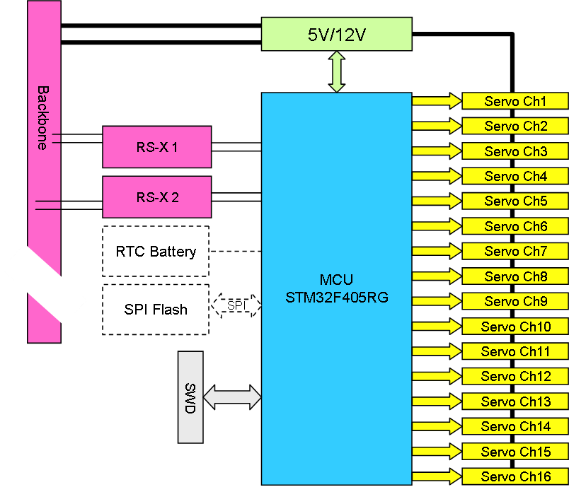
I will use 16 x 3xRight Angle Headers and some jumpers to select between voltage. I will only support 5V & 12V and max 10A in total. Higher voltage or effects will need to get their power directly.
Supporting 16 channels this way is a bit much as the total current usage can be quite high so I will add current sensors to monitor usage. I also need an inductor to prevent pulses from going back to the backplane. I need to review the 5V here because we currently only have a single 5V supply that also is used for the MCU. I probably need to add a 2nd 5V on the backbone to allow for separate PSU’s for modules connected to actuator/servos.
In this case we also need to feed the 3.3V MCU from the 5V/12V used for the servo’s as we otherwise might not have a ground to our signal. Communication with backbone is RS-485 based on differential siganaling not depending on anything but those two wires, so this will work fine. It also means that we will no connect to the 5V MCU/Ground at all on this module. This actually raises a question if I should switch to isolated RS-485 towards the backplane here.
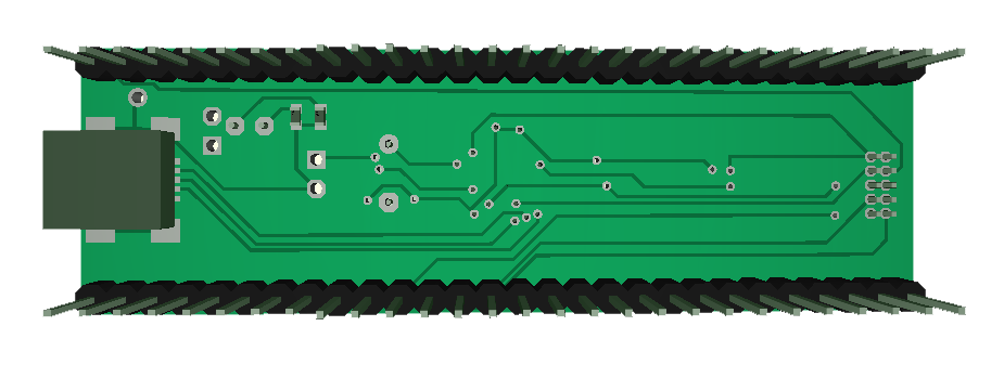
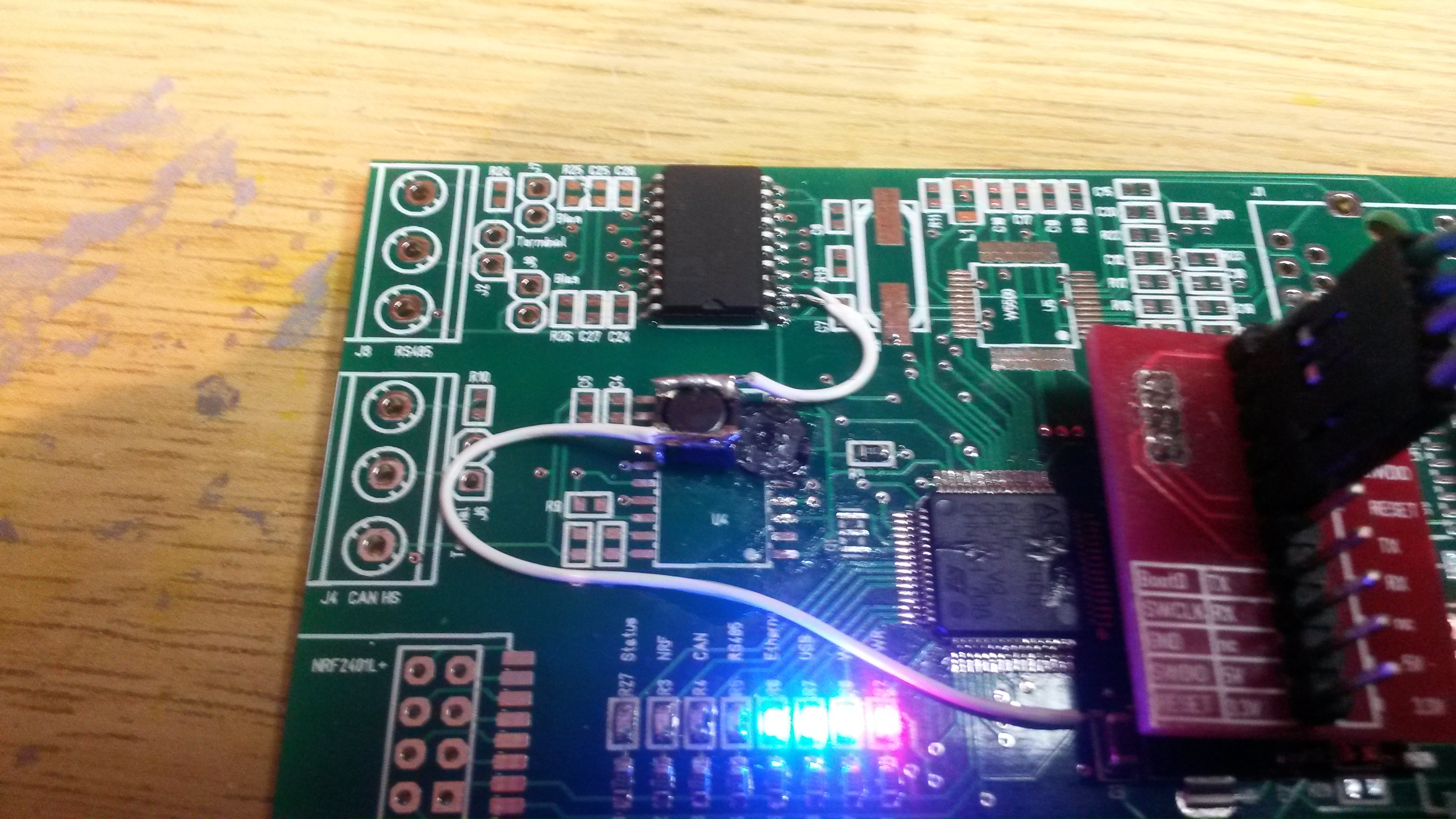 The black “dot” in the midle With wires is a 15uH/1A coil. I cut the 5V to ADM2582E on the backside and re-inserted 5V through this coil – now it ticks perfectly. If I short the coil it stops. I still need to add bypass capacitors, but this is a reminder how important these coils are to separate frequencies.
DPS5015(0-50V/0-15A) and DPS5020(0-50V/0-20A) are DIY modules available for ca 40.- USD. It exist several of these. Notice that input here is 60V DC, so you need a AC/DC converter in front of this.
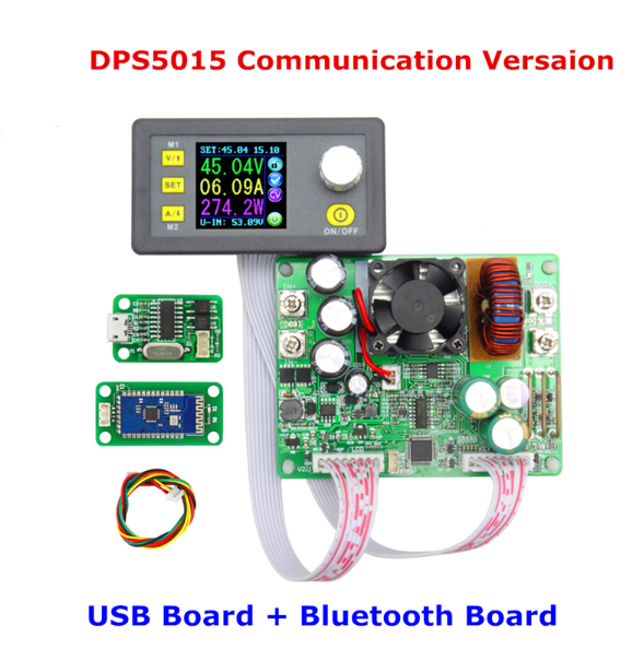
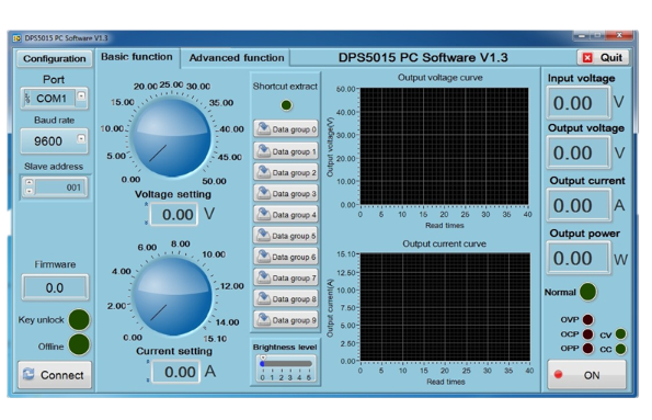
I have looked at these for a while as I plan to build some Lab PSU’s. It is an interesting option. The USB/Bluetooth adapter with the software below is very interesting. The module uses a UART With Modbus RTU – the protocol doc is in Chinese, but I hope someone will translate this to English.
One can never have to many lab PSU’s ….
I need to see if I can prevent the ADM2582E from creating noise so I can run the MCU at 168Mhz with this precent.
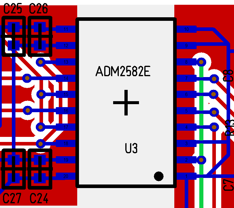
This is my current PCB around the ADM2582E. I only use 2 layers and could have needed 4 here, but the main problem is that I dropped the bypass capacitors on the right side facing the MCU – it would also help if I mounted those I have PCB support for. I believe the green lane (5V) is my problem – I want to cut this and introduce a 15uH-47uH/1A coil to stop high frequencies.
So adding bypass capacitors and a coil I believe I might have a chance to get the MCU ticking without failing – this is a bit out of my electronic skills, but it is a learning process.
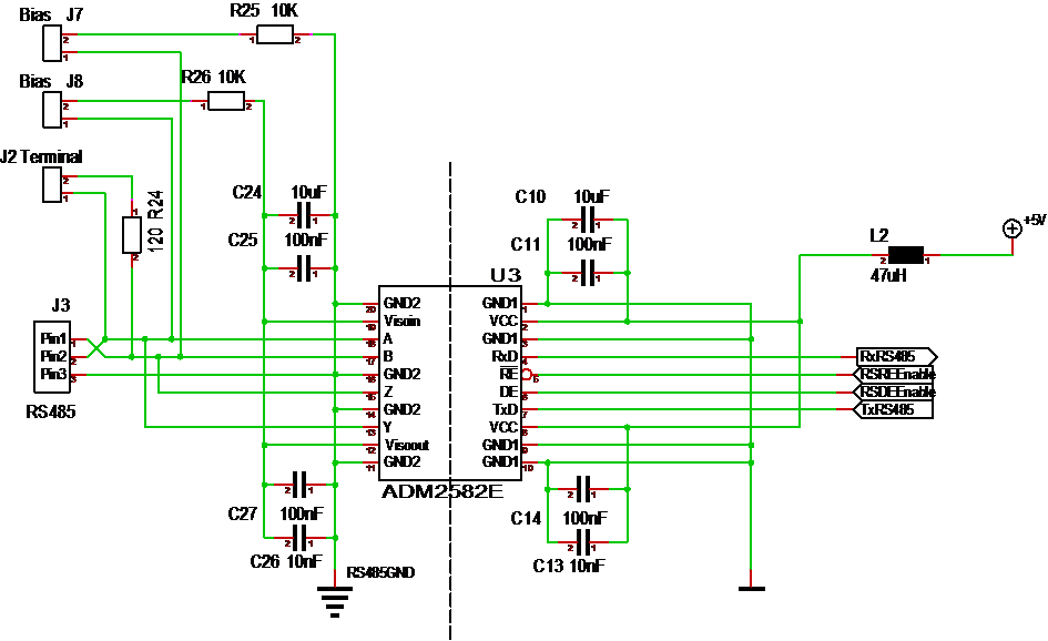
The schematics above is the New I want to make – C10,C11,C14 & C13 are the bypass capacitors I am missing. L2 is the new coil I want to add to stop high frequencies from “crawling” on the 5V. Will see if I can add this to one of the existing Boards for testing.
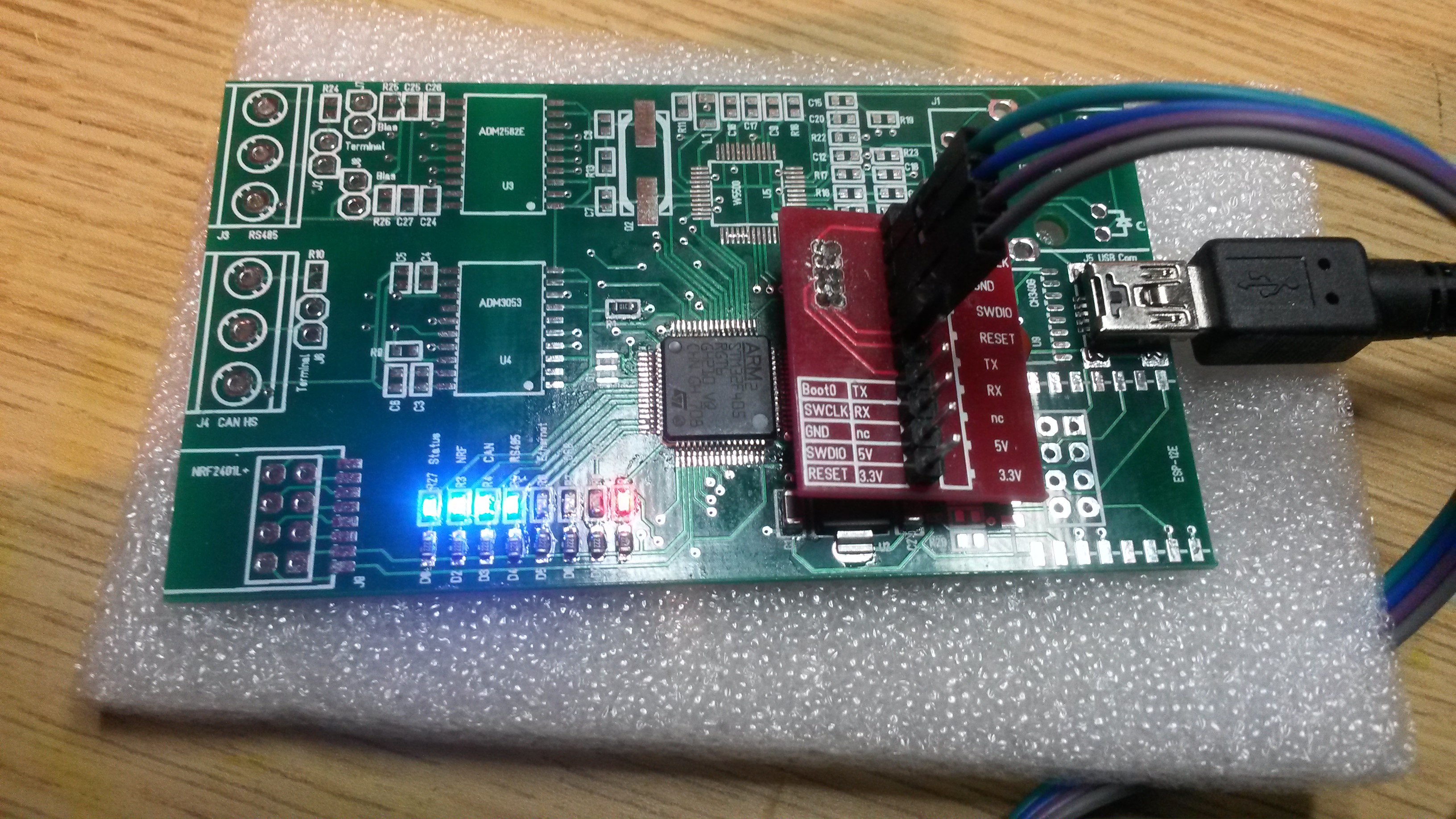
Mounted a STM32F405RG from a new batch I have and it works perfectly at 168Mhz. It just hit me that the other board have a ADM2582E mounted so I removed that and that board/MCU suddenly works at 168Mhz as well. It’s no question, I moved the ADM2582E to the New board and the board suddenly don’t work at 168Mhz.
ADM2582E contains a DC/DC converter that seems to be the cause of problems here. Reading the datasheet and app notes I seem to have stepped into a few issues on the design/PCB needed to reduce EMI noise – it’s a 180Mhz oscillator frequency for DC/DC used on that chip …
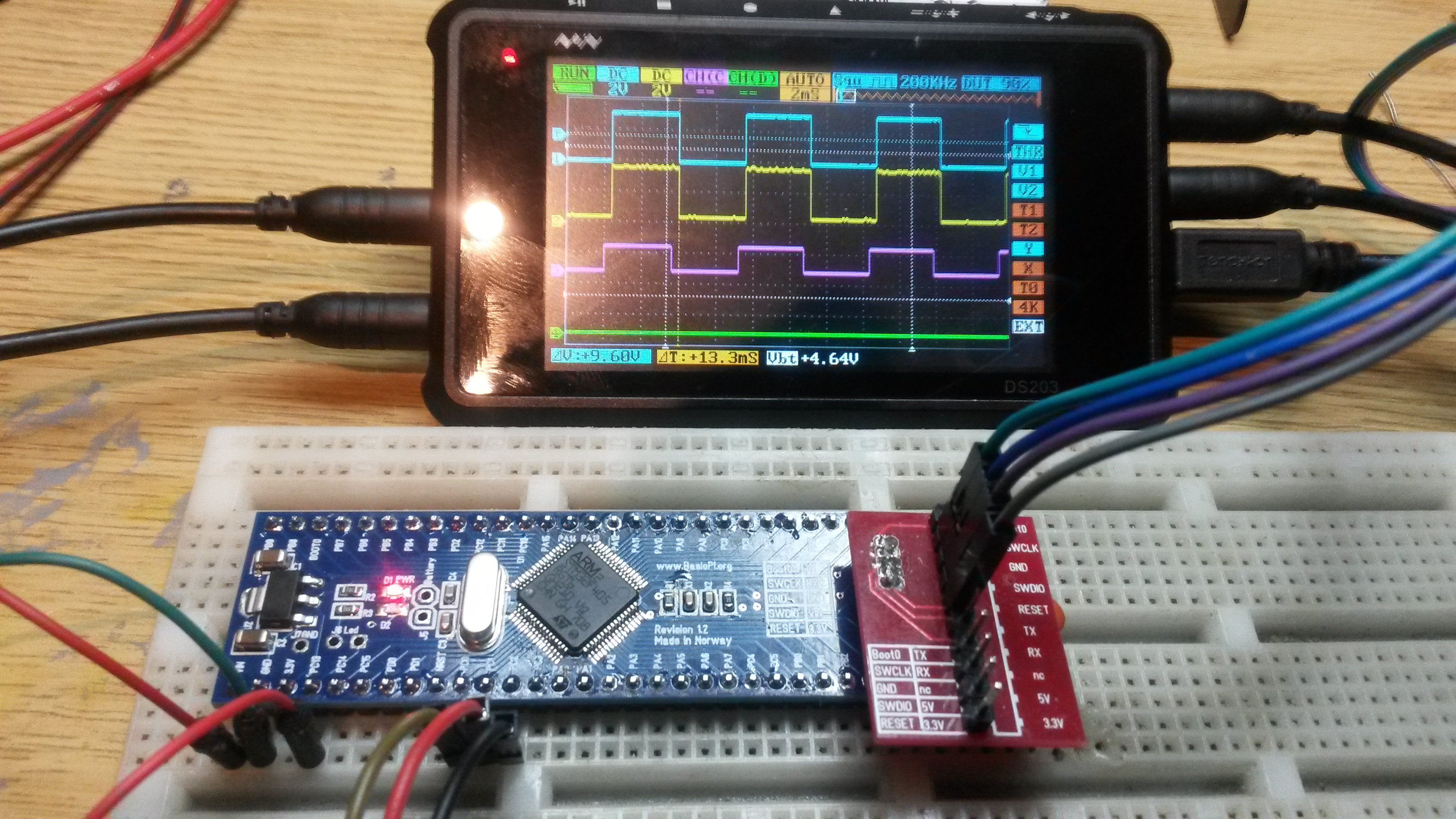
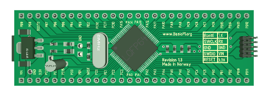
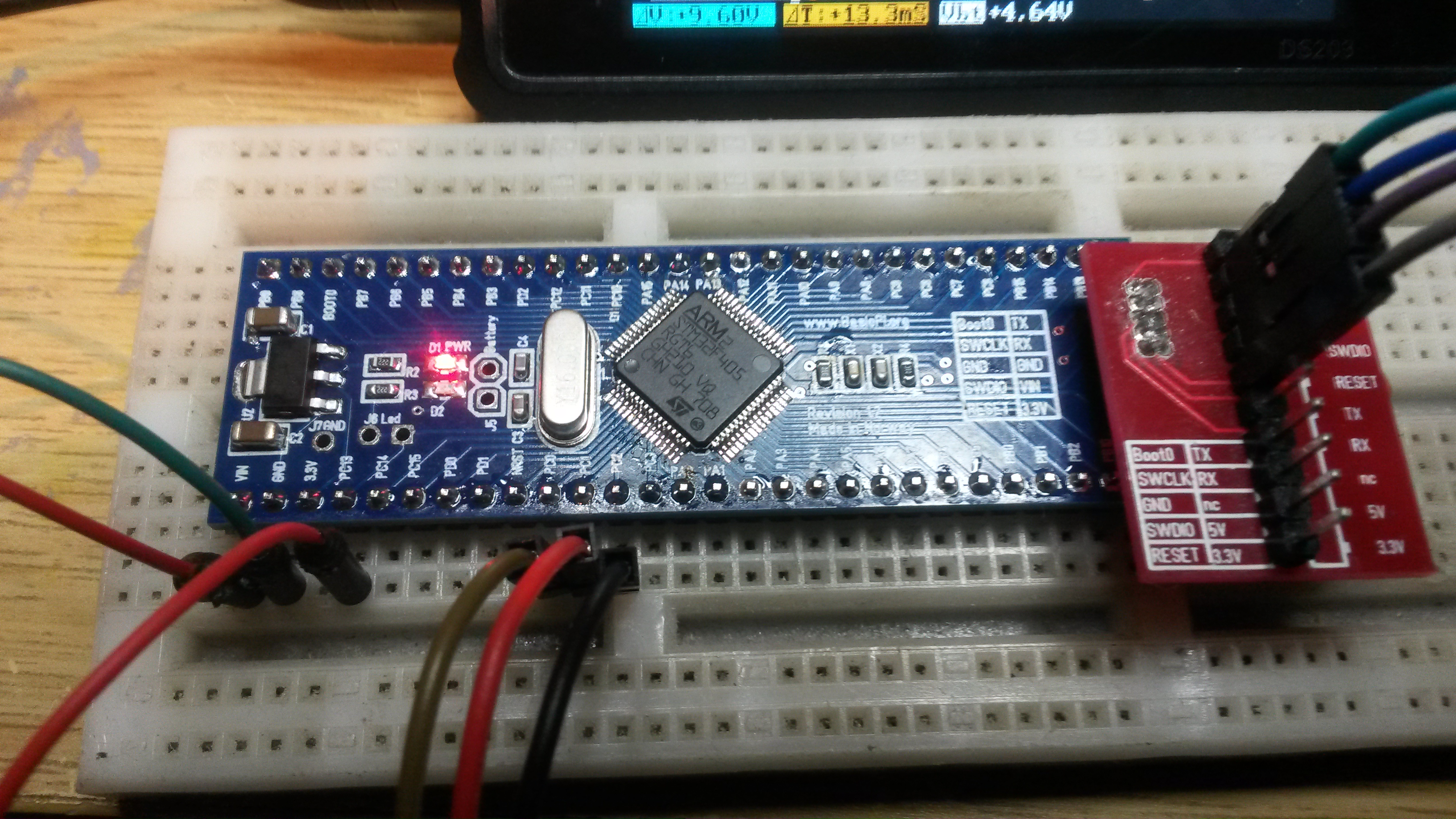
Mounted a 16Mhz crystal so ticking at 168Mhz HSE here. The oscilloscope is my DSO203 4 channel. I use it then I get tired of listening to the fan’s on the larger one. A better pic of the revision 1.2 breakout with a STM32F405RG below.
The 3D models below is actually the draft of revision 1.3. I decided to add a USB FS port and RTC 32.768Khz crystal as options. The USB connector is in no-one’s way if it’s not used and the RTC crystal can be removed. It’s capacitors are on the back. The reason I am adding these is because an USB is an excellent power connector + ST deliver SW to allow it to be used as a serial port. All of this is optional anyway.