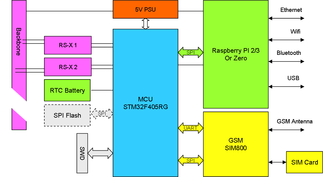
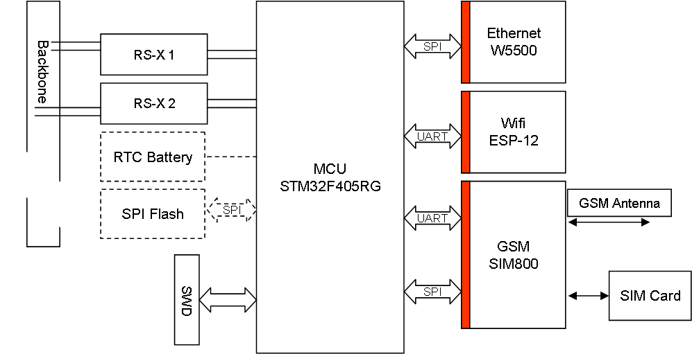
This one have a lot of potential as we basically create a Raspberry PI Hat that is a PLC Module and contain SIM800/SIM808. It makes a lot of sence doing this as a RPI Hat because I need RPI to do the more advanced voice processing for speech services.
New Ethernet/GSM Module
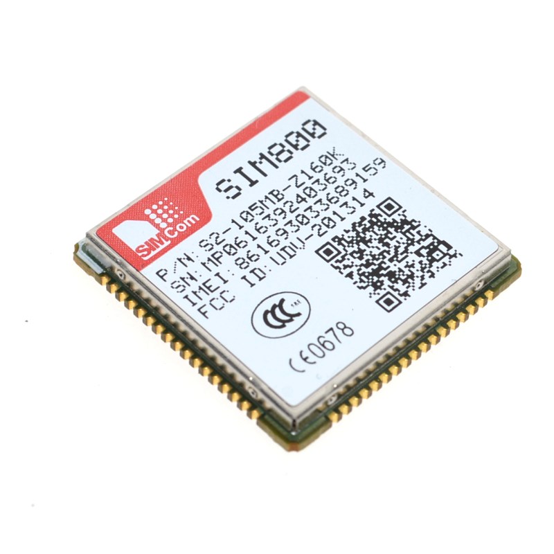
SIM800 & SIM808 GSM Modules
I initially wanted SIM800C because it support voice calls and it does analogue voice. My first idea was to connect this to a ADC/DAC on the MCU for digital voice services, but this is a bit complicated and involve a digital to analogue to digital conversion that I would avoid. What I need is “digital audio” support or more correctly PCM.
PCM is a “linear” version of the a-law/u-law used in telecommunication. The interface is 16 bit and uses a sampling rate of 8000Hz that is standard in legacy phone systems. SIM800 & SIM808 are two of the modules that offer a separate PCM interface as a bit-bang protocol.. The PCM interface on both modules can probably drive a SPI in Slave mode directly (not sure). The main difference seems to be that SIM808 include GPS.
Both these modules are a bit larger than SIM800C, but they offer a much nicer path to sound support from the MCU.
Ethernet/GSM Module
I can use my Universal Communication Adapter to code most of what is on this card, so I am in no hurry to order this PCB. The fact is I miss package sizes, so I just need to sit & wait a little for now. I am however running out of space in front, so I am considering increasing the size from 65mm to 75 or even larger. I am going to draft some of the other PCB’s to make up my mind.
I dropped sound support on this and I am a bit disappointed with the need for a 4V/2A PSU that require some extra space. This makes the GSM module much larger than you expect it to be. One nice thing about this PSU is however the digital on/off pin enabling me to switch off GSM power completely. I am drafting with SIM800C to get experience, but I have not decided what module to use yet. It is sometimes very difficult to choose without experience so you see what the differences mean.
I selected SIM800C over M590E due to sound support, but as I realize that sound is analogue only I need to look into the other (and maybe far more expensive) modules for digital sound support. The issue here is that using am ADC/DAC is possible, but as the sound is digital inside the GSM module I would rather swap to a module that offer sound IO on digital packets to avoid the extra noise. I need to work on this a little – nothing is settled yet.
I am also considering moving the GSM module to the top to let the antenna be on “top”. to avoid that it is in the way of Ethernet/Wifi.
Also, the difference between this and the All-In-One Home Central is very small at present…
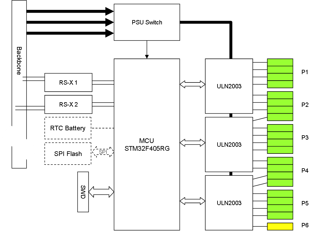
PWM Module 21×5-48V/0,5A
This makes use of the ULN2003 that can take 5-50V input and drive 0,5A. This simple chip allows for multiple PWM channels that can be used for anything from relays to small steppers. This draft suggest 5 stepper motors and a actuator. The connectors on this is a Challenge due to the available width.
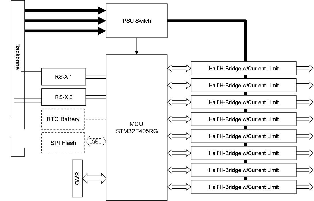
PWM Module 8×12-48V/3A
This draft illustrate a PWM module based on the driver of the motor controller we made earlier. We use a concept of a gate driver and 2 x HEXFET to create a Half H-Bridge. We will need 10V+ due to the gate driver, but we only need 1-3A on this one. I think it is realistic to have 8 channels, but if not we will reduce the numbers. PWM out will be anything from constant voltage to 0 duty. We will pulse on/off and use a 2nd frequency to pulse (regulate voltage) within the main pulse.
This targets solenoids with 12-48V and <3A.
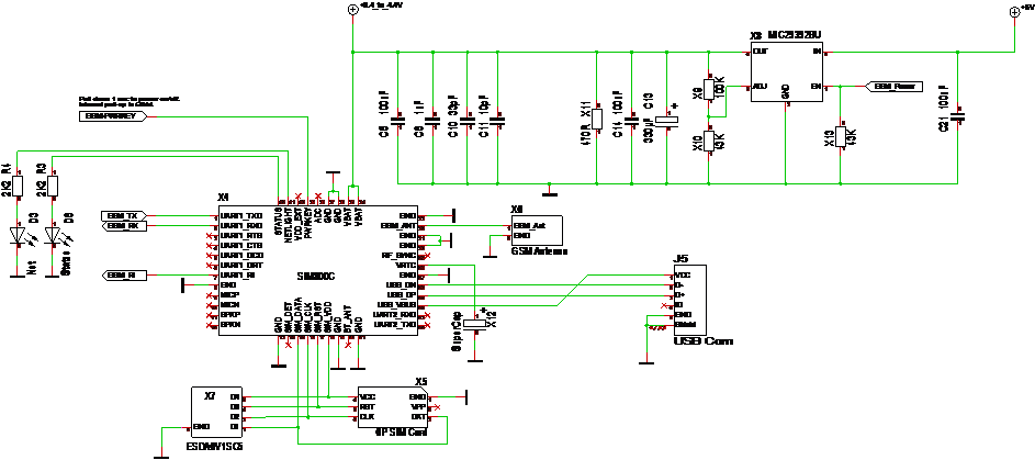
GSM Schematics
Double click on the picture to see the larger version …
The SIM800C uses a 4V PSU that need to support 2A. All the circuitry on top is PSU related according to reference – I have removed some, but need to see the PCB layout before I consider the rest. Also, I am not sure I bother With the USB Interface. But, well it’s an ealy draft anyway…
I have not Connected the voice on the Ethernet module due to Space concerns.
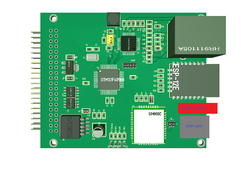
Ethernet Module
Just an early 3D model of the Ethernet Module including Ethernet, Wifi and GSM based network connections. I have to add the 3D modules of the sim card holder and antenna that also goes to the front, but I am running out of space. These modules are only 80 x 65mm, but that is in my opinion needed for mobile PLC’s.
Plain – hitting the road
I wrote lengthy blogs about Plain syntax and concepts earlier this year and want to wrap up the specifications and get going. The challenge with pushing on ideas and concepts is that you start getting blind-folded and stuck as you push for results. This is why I prefer new concepts to mature because what seems like a good idea one day might not the second day. Many of the concepts in Plain have however evolved over several years as I started on this far earlier than this blog.
The difference with other programming concepts is that I don’t want to create another language, I want to evolve the way we work so we can achieve more with less. Plain embrace several new concepts aiming for that, but this is untested theory. I believe it will work as expected, but I am also prepared for setbacks as we move forward.
Plain is also more difficult to achieve than normal programming languages because I need electronic devices supporting it and an established infrastructure to build on. Things take time, but we will get there.
Thanks for reading.
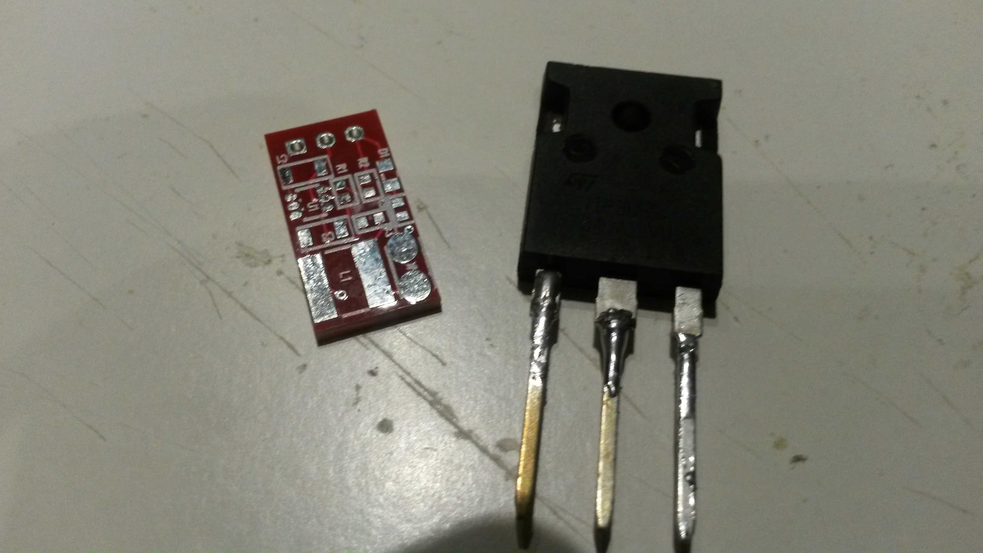
3.3V 5V, 12V or 15V Switched PSU
This is the PCB for my switched PSU. It takes 40V in and can be made to produce 3.3V, 5V, 12V, 15V etc. With Pictures you loose a bit feeling of the actual size, so I put a TO247 transistor next to it – this is the smallest PCB I have made so far.
It is designed as a drop in replacement for linear regulators since I often need 2-4 PSU’s on a motor/PWM design. Regulating from 40V to 3.3V means you use a lot of Power. Will assmble a few of this for testing later.
