PSU 36V / 5V

I purchased this for < 12.- USD and tried it as a driver stage for DPS5020. It works fine. It is small and perfect for a 0-35V / 0-6A “bread & butter” lab PSU. The DPS5020 have a cut-off setting that I set to 6A. It cut’s the PSU if you by mistake allow more than 6A out to protect the driver stage. The driver is also short-cut protected.

  • Driver PSU : 12.- USD
  • DPS5005: 25.- USD
  • Box : 17.- USD
  • Mix: 10.- USD

That is 64.- USD for a single 0-35V / 0-5A and 101.- USD for a dual. And this Lab PSU will have far better spec than any of the “cheap” ones. Also keep in mind that DPS5005 is much smaller than DPS5020 as it hide the PSU inside the HMI unit.I notice that Input Voltage to DPS5020 variates with +/- 0.05 as I use the Driver at 5A. I will put a oscilloscope to see if I have ripple later.

I had to abort the test yesterday after ca 10 minutes because my load started to melt 🙂 – we have some awesome Lab PSU’s coming up. DPS5020 do have a small fan, but it has been silent so far.

Adjusting Voltage/Current on these modules are a joy- Just select V or A and turn the knob. Push the knob to change digit you adjust. With a MCU using ADC’s we have an accuracy on ca 0.02ich – which is pretty good compared to analogue PSU’s.

What we have not discussed so far is output filtering. With some of these giving 50V – 20A we will be giving 1KW out. That is 1KW that will spike back as 1000V with 1KW energy if we have coils/motors connected. We need to ensure that the PSU can protect both itself and the equipment we are testing.

DPS5020 Review 2

The interface on the UART is Modbus RTU. I managed to translate the document from Chinese to English yesterday, so it is uploaded on the download page. Running the top-side app was straight forward on Windows 10. I had a bit of issues with antivirus installing it, so had to switch that off. The graphs are cool, but the window scale is a bit short and it only update once a second. Testing current under load was however a beauty. Using 36V in (3 x 12V/10) I had no problems with 10A out – or more correctly my load and test wires did get hot.

DPS5020 Protocol Specification 1.2 can be found on the download pages here.

Using UART/Modbus as interface it will be straight forward to create a custom HMI module to add buttons and display graphs on the box without a PC.

PSU Driver

The diagram above show the minimum needed for any mains PSU. We need a On/Off switch and a fuse. This can be purchased as a single unit. The 2nd is the PSU itself that is available in numbers on the net in nice modules.

A 12V/10A module cost < 10.- USD and they can be connected to create more current or higher voltages. Using 5 modules you can create 60V/10A at a cost of < 50.- USD. Using multiple modules like this can save some cost, but it usually require more space. As illustrated in an earlier entry the Driver stage is actually more expensive than the DPS5020.

Please check the regulations of your country before connecting anything to the mains.

Programmable Lab PSU 0-50V / 0-20A – DPS5020 Review

I received a DPS5020 module yesterday, well packed. This is the 0-50V/0-20A Lab PSU module I mentioned earlier. Assembling and switching this on was straight forward, and using it was a very positive surprise. I was initially concerned about it’s HMI, but I am actually impressed by the cleverness of this design.

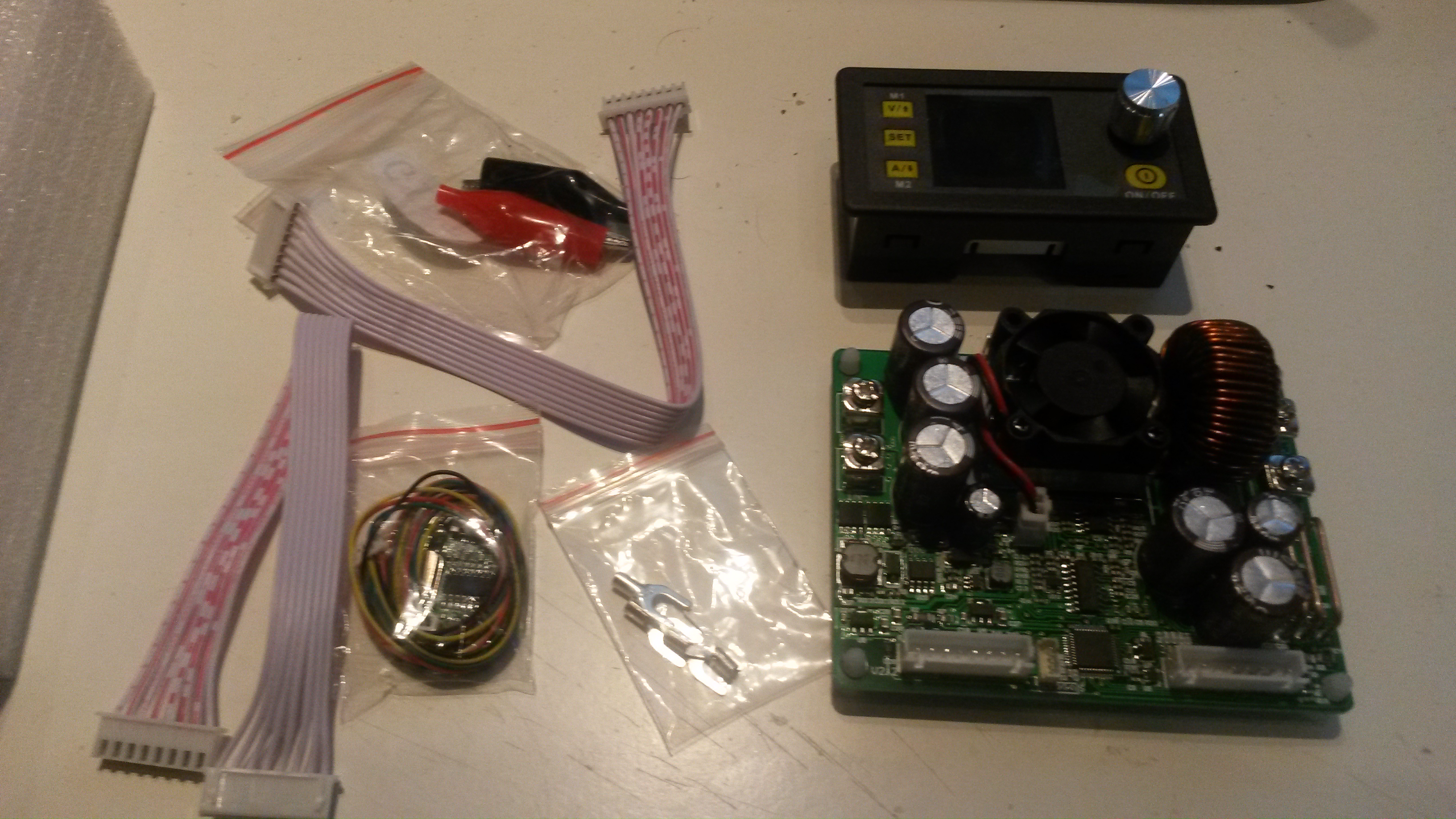
This first picture (sorry for the quality) show what you receive. A small user manual, cables and the two main modules. What surprised me a little is actually how small this is, but I need to remind everyone that you need a 6-60V DC supply in front here. I applied 30V and get an output from 0-29V. The HMI sence the input and adjust on Voltage range accordingly. I will see if I can do the same on current (manually set upper limit)

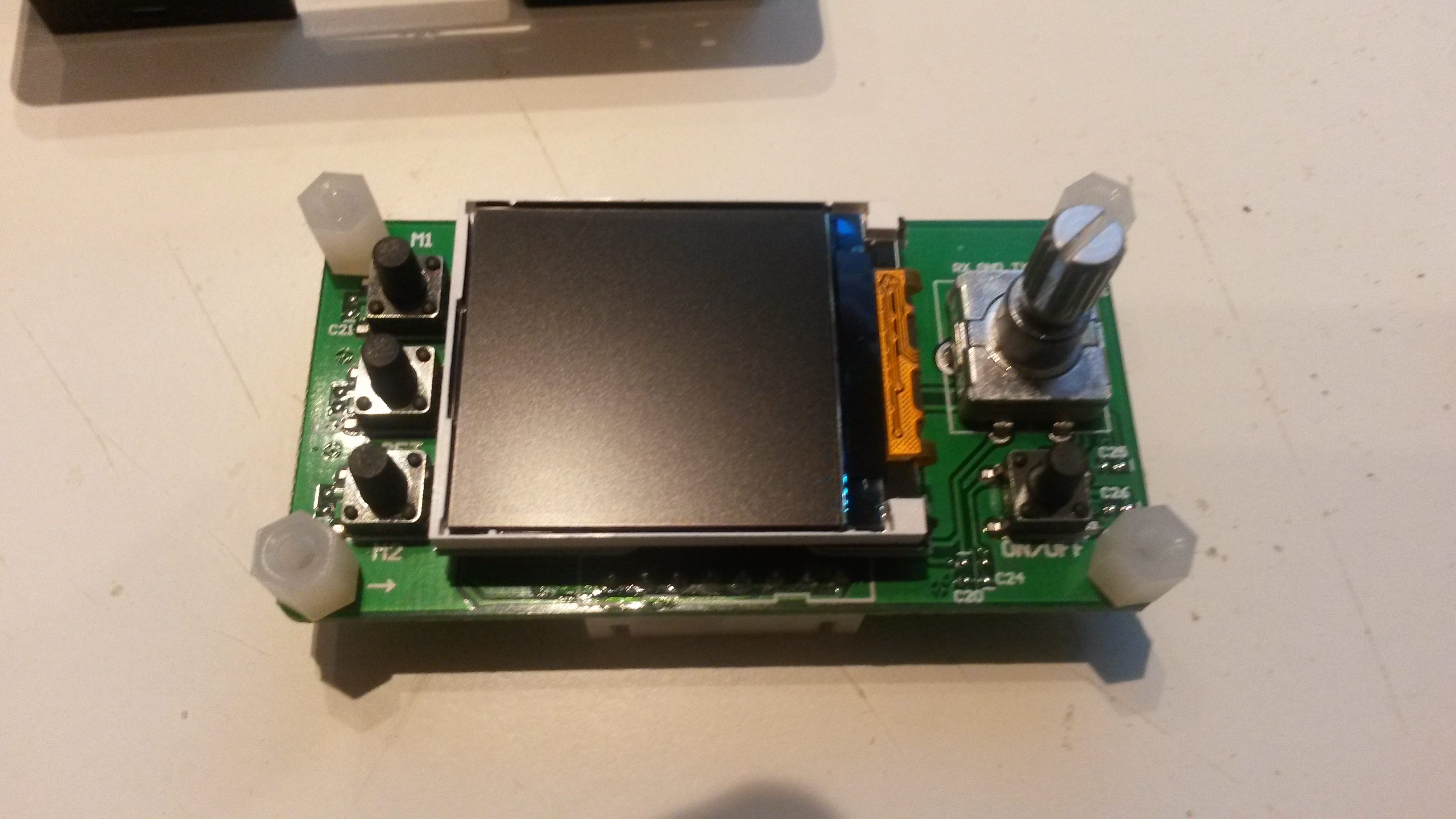
This picture show the HMI module opened up. The display is small, but sufficient. The entire module is quite simple and could easily be replaced with some hacking – it has a separate LCD and Keys cable, but I have no info about their pins jet. My initial plan was to replace this, but after having used it a little I am not so sure I actually want to.

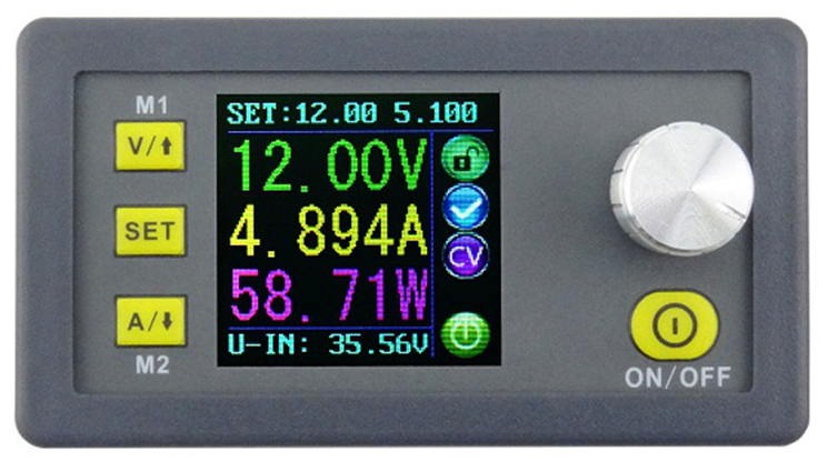
This is a picture (from the net) showing the HMI in use. The Green/Yellow/Purple text in the middle is showing actual output. On bottom (cyan) you see voltage in, on top(cyan) you see Voltage and Current setting. Notice that Voltage out show actual voltage out, not the intended setting. You will actually see a +/- 0.01 variance in this.

Operating this is straight forward – press V and turn the knob to set Voltage, Press A and turn the knob to set Current limit. Once you are done you press Set and get a confirm screen. After that you press the On/Off to enable this out. This took me by surprise because it is not just about turning the knob to change voltage – you actually have to press V button first. This is very good because it is nice to know that your PSU don’t change by accident. You can adjust voltage both on-line and off-line this way. The second issue is the capability to adjust setting before you enable it out. The knob is a standard encoder with a push switch used to change what digit you adjust. Seriously it took me around 60 seconds to learn this interface. This is far, far better than I actually expected.

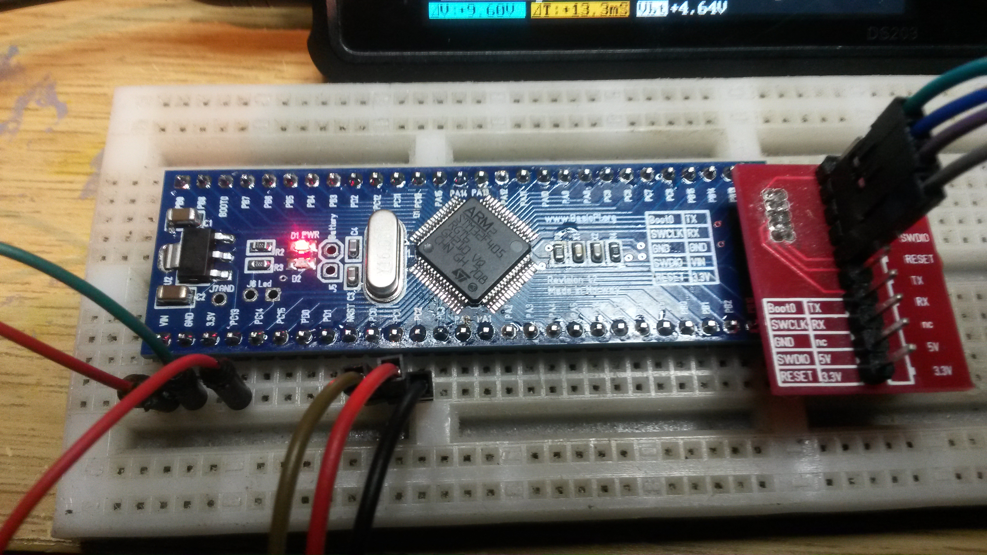
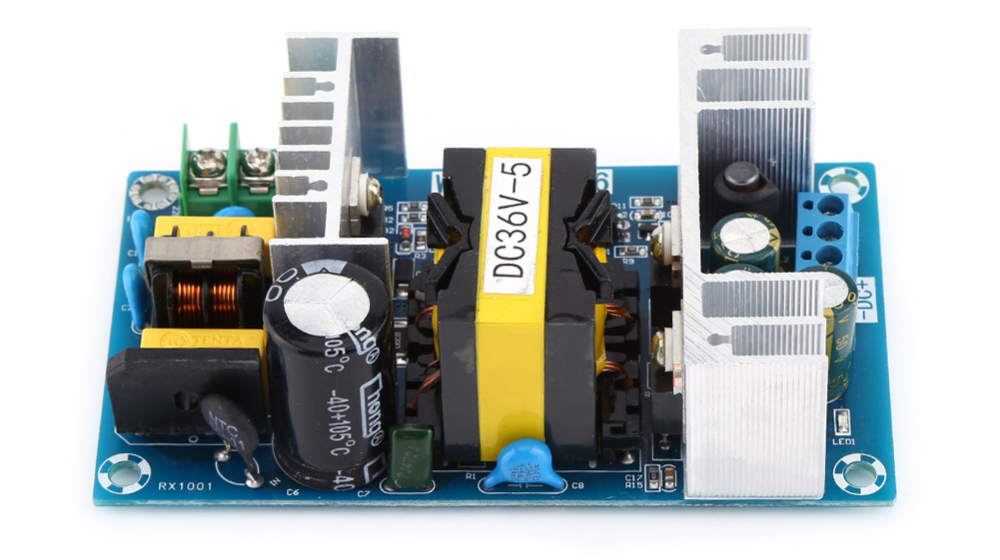
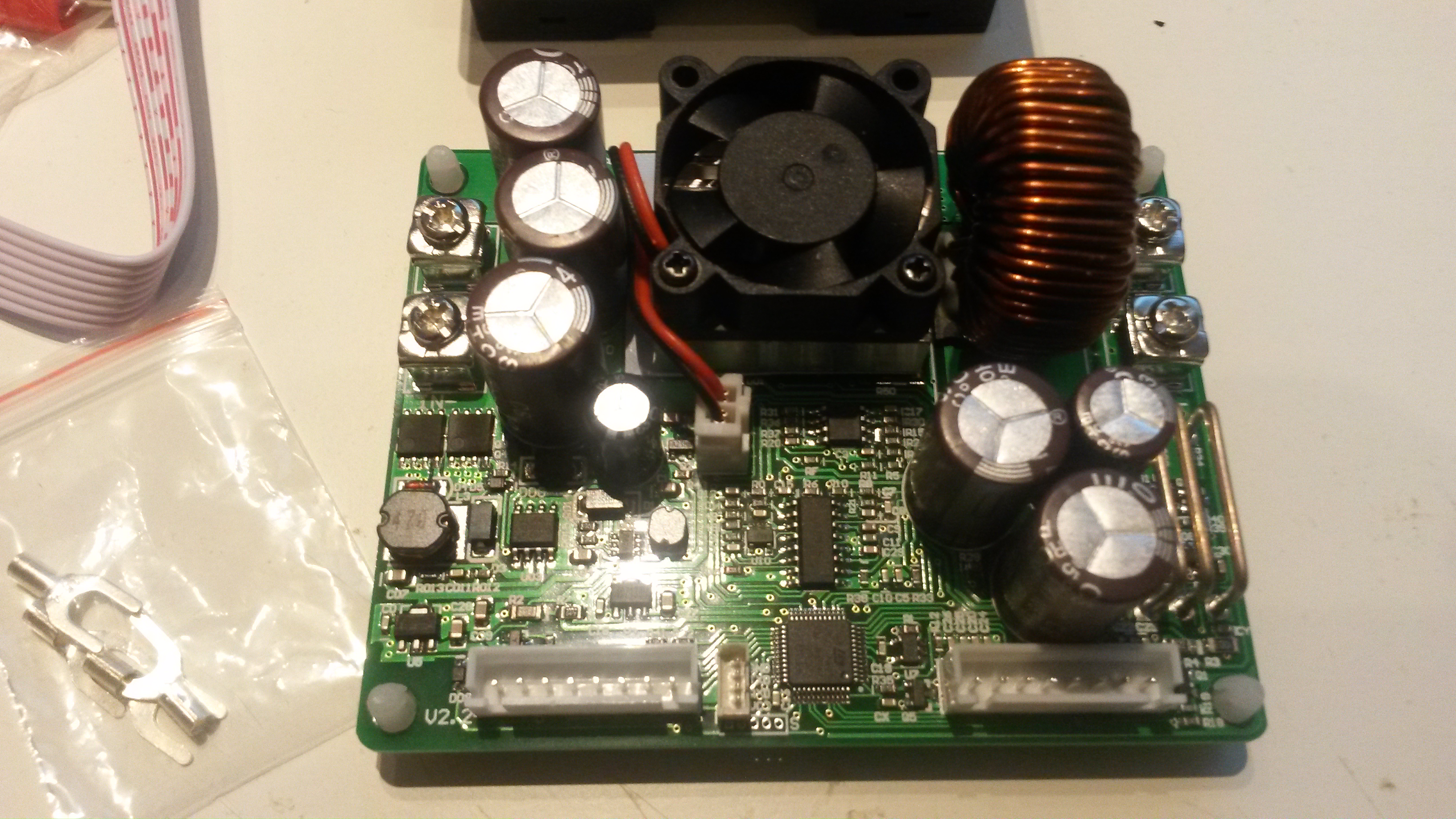
This is the PSU module itself (above). Input at left, output at right. On the front you see a LQFP48 holding a STM32F100C8. I ordered the USB which is a familiar CH340G operating on an UART. That is the small 4 pin connector next to the MCU. I will get back to using this, but it basically means you can remotely connect to this using USB, Bluetooth or simply hacking the UART. I believe the protocol is described.

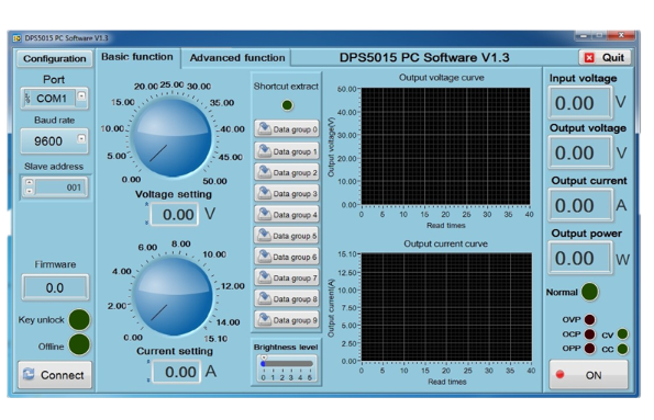
This is the included top-side HMI that can be used to operate this from a PC. I have yet to test this. You need to downoad this from their site – this pic is actually from the 15A module. My comment here is that this is all fine, but I need my PC screens for different purposes. I would however like the graphs, so I am considering hacking the UART and connect a Graph display on the PSU + adding Ethernet/Wifi capabilities.

Next I will get some load tests done to see how this wonder behave under heavy usage. Not bad for 45.- USD P&P included. Transport was under 3 weeks, but this is only pure luck.

Smart SPI Test Kit

This is the test suit for Smart SPI. This is an old pic, but I will upload a newer one showing RPI mounted behind the 32xServo and how we access SWD & Raspberry PI for development.

The mechanics of thos robot is dodgy, but it is a very good and fun test kit. I also have a different robot that we can have some fun with during testing using the 8x DC Motor hat.

Keep in mind that Raspberry PI Zero W provide both Bluetooth and Wifi – I only need battery added making this a very easy and scalable design.

Adding more Hat’sm we can scale up and we basically have a PLC style design with Raspberry PI as core. I have a few more Hat designs coming up, but once I have tested this I will try putting this into volum production through kickstarter.

I have no idea about prices yet, but I hope we can achieve ca 25.- USD or lower. This is no-profit, but the key is that I need volumes to push prices down. I also need to engange professionals for CE/FCC tests. I am not so worried about the later, as Wifi/Bluetooth is dealth with by 3rd party, and this is only a component – but, we need to test that we don’t have nasty signals by accident.

Smart SPI Driver

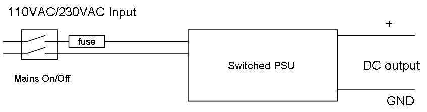
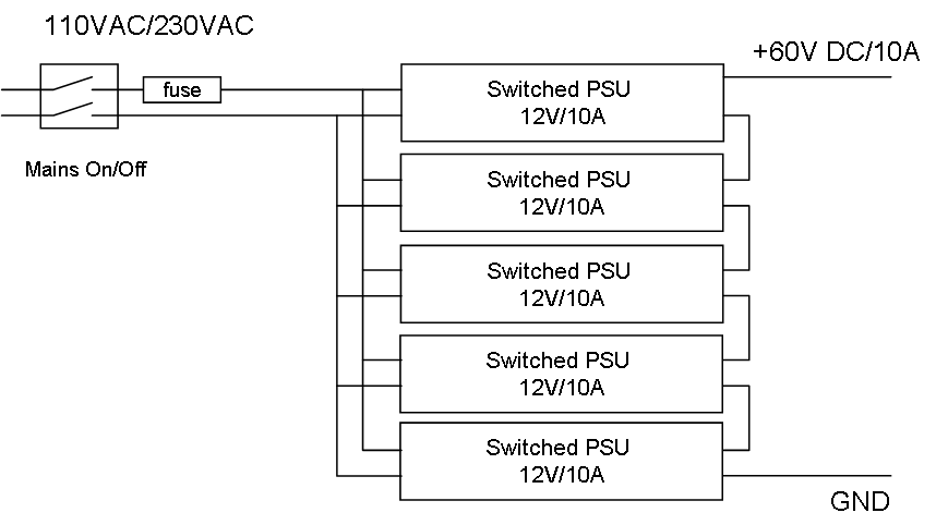
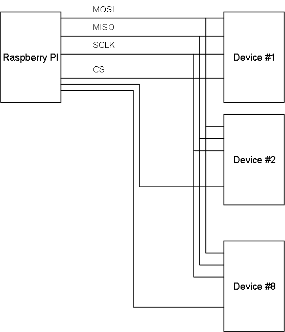
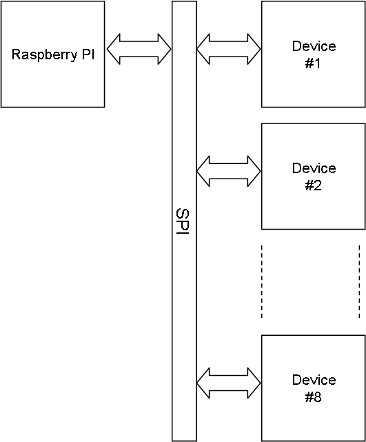
I need a specialized SPI driver to support the Smart SPI concept. The block diagram above show the logical view with device to device communication, while the diagram below show the physical design. Just to remind everyone – in the logical concept we communicate device to device. In the physical this is done by a device sending a message to RPI that send it to the addressed device.

A classic SPI will enable a CS, communicate with that device before it continue to the next device. As discussed before this is not optional as it do not take into account the actual stream queues, so we will implement several important tweaks to optimizeSPI communication efficiency.

We will only use the CS for ID procedures at start-up. I am currently looking into even drop this. Each device here is intelligent and capable of filtering out it’s own messages. They also have 3-state capability allowing them to listen only while only one respond back. This enables a free flow where RPI have a continuous send with a soft-switch selecting the device that communicate back.

This requires specialized SPI drivers both for Raspberry PI and STM32. The advantage for Raspberry PI is that we allow Linux to use deep DMA queues and avoid CPU heavy bit-banging. The only dissadvantage is a complex SPI driver.

My current Hat’s support CS addressing using a classic address selection. I am considering ditching that and set the MCU address directly with 3-4 GPIO pins. The drawback is that I need to modify all Hat’s, but that is doable since none are in production yet – and I am commiting to using a number of pin’s for address setting. The usage will be the same as before, but we drop the SPI ID procedure because it is not needed anymore. At precent I will focus on a single Hat, so I can pick up this as I make the next revision of the Hat’s. It also gives me time to mature this change a bit.

Home Automation Central

I have already talked about using this module as key for a home automation central. I am going to look into a few extensions (or additional module).

A normal wireless have a range on ca 100m, but dealing with home automation you could use 1Km range – solutions for that exist.

Another change is the capability to use this as a wireless router creating a privat, wireless sone that can be extended.

The alternative is 1km long twisted wires for RS485 or modem’s, but a wireless solution is so much easier. I will be back on these extensions later.

32 x Servo / IO Capability Map

This table is a all 32 channels on the 32 x Servo / IO Hat mapped out per channel. Explenation under the table.

Ch1 PC1 Analogue In
Digital In
Digital out
Servo
Software PWM
Ch2 PC2 Analogue In
Digital In
Digital Out
Servo
Software PWM
Ch3 PC3 Analogue In
Digital In
Digital Out
Servo
Software PWM
Ch4 PA0 Analogue In
PWM
Digital In
Digital Out
Servo
Software PWM
Ch5 PA1 Analogue In
PWM
Digital In
Digital Out
Servo
Software PWM
Ch6 PA2 Analogue In
PWM
Digital In
Digital Out
Servo
Software PWM
Ch7 PA3 Analogue In
PWM
Digital In
Digital Out
Servo
Software PWM
Ch8 PA4 Analogue In
Analogue Out
Digital In
Digital Out
Servo
Software PWM
Ch9 PA5 Analogue In
Analogue Out
Digital In
Digital Out
Servo
Software PWM
Ch10 PA6 Analogue In
PWM
Digital In
Digital Out
Servo
Software PWM
Ch11 PA7 Analogue In
PWM
Digital In
Digital Out
Servo
Software PWM
Ch12 PC4 Analogue In
Digital In
Digital Out
Servo
Software PWM
Ch13 PC5 Analogue In
Digital In
Digital Out
Servo
Software PWM
Ch14 PB0 Analogue In
PWM
Digital In
Digital out
Servo
Software PWM
Ch15 PB1 Analogue In
PWM
Digital In
Digital Out
Servo
Software PWM
Ch16 PB2 Digital In
Digital Out
Servo
Software PWM
Ch17 PB10 PWM
Digital In
Digital Out
Servo
Software PWM
Ch18 PB11 PWM
Digital In
Digital Out
Servo
Software PWM
Ch19 PC6 PWM
Digital In
Digital Out
Servo
Software PWM
Ch20 PC7 PWM
Digital In
Digital Out
Servo
Software PWM
Ch21 PC8 PWM
Digital In
Digital Out
Servo
Software PWM
Ch22 PC9 PWM
Digital In
Digital Out
Servo
Software PWM
Ch23 PA8 PWM
Digital In
Digital Out
Servo
Software PWM
Ch24 PA9 PWM
Digital In
Digital Out
Servo
Software PWM
Ch25 PA10 PWM
Digital In
Digital Out
Servo
Software PWM
Ch26 PA11 PWM
Digital In
Digital Out
Servo
Software PWM
Ch27 PA12 Digital In
Digital Out
Servo
Software PWM
Ch28 PB3 PWM
Digital In
Digital Out
Servo
Software PWM
Ch29 PB4 PWM
Digital In
Digital Out
Servo
Software PWM
Ch30 PB5 PWM
Digital In
Digital Out
Servo
Software PWM
Ch31 PB6 PWM
Digital In
Digital Out
Servo
Software PWM
Ch32 PB7 PWM
Digital In
Digital out
Servo
Software PWM

Analogue In means it has an ADC capability on the channel. This can sample at a very high frequency. It is 15 of these

PWM means we have a Hardware PWM signal with a very high frequency capability. It is 23 of these.

Analogue out means it connect to a DAC. It is 2 of these,

Digital In & Digital Out is on all 32 channels.

Servo is available on all 32 channels and is the default configuration.

Software PWM means we bit-bang the pin in software to create a PWM signal. Max frequency is ca 10KHz. Available on all 32 channels.

An updated version of this table can be found in Annotated Schematics (coming soon). Pin’s have all cababilities as per STM32F105RB capabilities, but more advanced features will need custom modified firmware to access.

STM32 with Visual Studio Code

Visual Studio Code is more an editor with debugger support than a full IDE, it takes a bit fiddling to set up and get right. Basically you don’t have any setup screens and have to edit your project in files with XML syntax. I am not sure if I will use this for everything, but VSCode has definitely come to stay – it simply is to handy to have around as code editor for various things alone.

VSCode itself is a framework that allow extensions to be added, and extensions exist for a lot of things. STM32 is currently supported through PlatformIO (www.platformio.org). Sadly the STM32 support is still a bit limited, so I have not been able to test to much and setting it up is a bit fiddly. PlatformIO IDE is not really free – they maintain a community version, but that seems to lack essential features to be of any real use.

One annoying issue with VSCode is that it’s folders are physical within a hierarchy – myself I arrange the project on top with a strict set of sub-folders. What IDE people use differs with developer so I like to hide this in sub-folders. That does however not prevent me from editing

All in All – Visual Code got my interest, but I am not sure about Platform IO yet – neither am I sure I actually could commit a full project to VSCode alone.