16 x Servo PLC Module

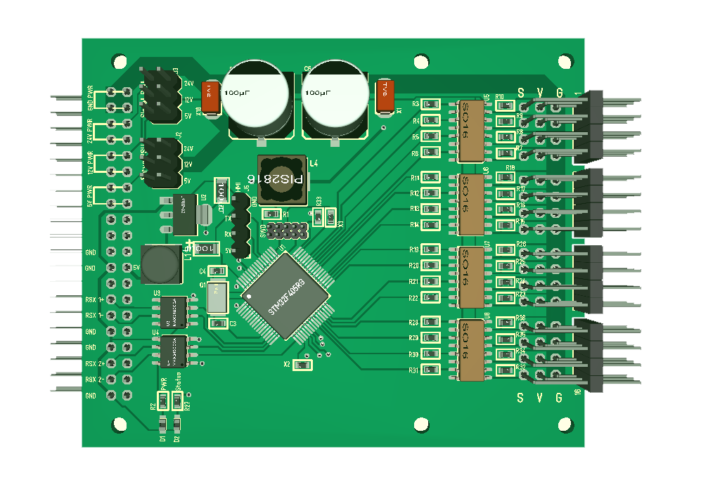
Added 2 coils on the 16 x Servo Module as well. On this I have plenty of space. I should have moved the MCU a bit down, but I will leave it for now.

This module provide output only, meaning it can not do generic IO as my previous 32xServo/IO could. The limitator is the opto couplers providing a full galvanic isolation.  It can still do digital output and low frequency PWM (< 100Khz) in addition to Servo signals.

Servo PSU is selectable from 5, 12 & 24V by jumper. Signal is also selectable from 5, 12 & 24V by Jumpers. The MCU 5V is separate from the Signal/Servo 5V etc.

It is also has a 4 pin HMI – the same as on the CCM board. I simply did not see any point in removing it + might be cool for demo/testing.

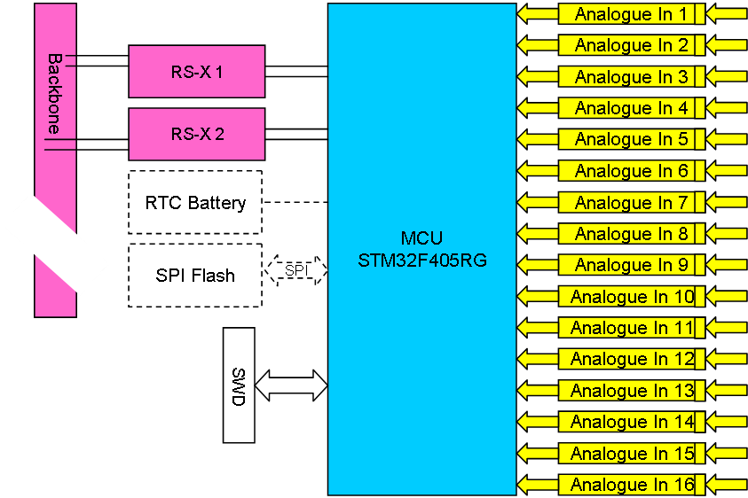
Doing 16 channel Servo on a STM32F405RG is well, the reason I use a M4 is the speed of the backbone bus.

CCM/PLC Module PSU Coils

Not very exiting – just added the 3 extra 15uH coil options I mentioned earlier on the back. As mentioned these are added because I suspect I need them to separate 5V PSU to different high frequency modules. The issue, as we learned earlier is that these freuencies interact. The coils here simply let 5V through but stop higher frequencies – it cost me little to just add the space for these on the back side.

I have a weird package error on the 25 Mhz crystal that I need to check, otherwise this is ready to go.

Also starting to use “CCM” (Communication Central Module) as name on this because it contains  Ethernet, GSM, GPRS, GPS, WIFI, Bluetooth,  USB++

PLC Modules

I updated the module list again – don’t worry – this will not be the last change here.

CCM (Communication Central Module) is the new name for the combined Ethernet, Wifi, Bluetooth, GSM/GPRS, GPS, RPI Module. I packed so much into this that it covered 3 planned modules.

Servo Controller Module was illustrated earlier.

I need to work on PSU/Battery.

3 x RS-X Module comping up.

8 x Analogue Input Module coming up.

PWM Output Module coming up.

Digital Input Module coming up.

DC/Stepper Controlles – we probably talk several modules here.

Sound I/O – now this becomes interesting. We have so far talked about a PLC that control robotics, but we could easily talk about a system that also does sound processing… I am very, very thin on analogue electronics, but some interesting options here.

Analogue Input Modules

These two diagrams show drafts of analogue data acquisition modules. The first is a 8 channel 24bit @30Ksps while 2nd is a 16 channel 12bit at 2,5Msps.

The ADS1256 is available for ca 5.- USD and provide 8 channels with 24 bit resolution at a sampling speed of ca 30ksps. This is very good for an ADC with this high resolution.

The faster ADC technique is achieved by using the ADC’s integrated in STM32 directly. These are 12 bits, but have a much higher sampling rate capability (2,4Msps).

I am not sure if I want to make both boards + I need to dig in a bit on analogue scaling & calibration options. I also need opto isolators that have limitations of their own. I also have the issue that the higher frequency of the 12 bit is of little usage + 12 bit resolution is a bit low for sufficient accuracy. Assuming I have space I could actually extend the 24 bit board with a few faster 12 bit channels as well.

Mobile Home Phone Central

One of the reasons I selected a PCM interface adding a digital sound connection was because it allows me to connect sound  to/from the MCU using I2S. As each GSM/GPRS Module also have both Ethernet & Wifi it is very easy to create a Mobile Home Phone Central with SIP Phones around the house. Using the fast backbone bus we can easily scale up to a quite large phone system. RS-X is a TDM protocol that is perfect for telecommunication, and bandwidth should in theory cover ca 60 voice channels on the backbone alone with 30-50ms algorithmic latency on the voice transport. Voice latency would actually be good because it is only static, algorithmic latency.

Keep in mind that this is 60 external lines only. Internal Ethernet/Wifi traffic will not be through the backbone. This design also have the advantage that we have an overkill in CPU power available in a truly distributed architecture.

This is a very interesting add-on capability to our Home Automation System.

Adding Coil/Inductor Options

Learning from my experience with a 168Mhz MCU interfering with a 180Mhz DC/DC I realize that I might need a similar option to separate the 4V PSU feeding the SIM808 on the module pictured above. In this case I would need a larger 2-3A coil related to 13 (4V PSU) above. This being a single side assembly I will add an optional connector for this on the back-side just in case.

Ethernet (W5500) already have a coil separating it’s 3.3V from the MCU.

 Raspberry PI Zero W also feed from the  same 5V – I need to add a coil option for this as well. What I will do is to add a connector that is shorted so that I can cut this and introduce an inductor if needed.

The last one is the 3.3V for the MCU itself. It feed from a 5V PSU that will feed several cards all running a 168Mhz MCU. I hope the linear regulator will do the filter job, but I will add an optional coil here as well – just in case.

I might also add some scope test-points + I will re-examin the SIM808 design – but after that I will order the PCB so I can start. I have to be realistic and expect that I will need 3-4 revisions before this module is working properly due to it’s complexity. I have evaluations boards we can connect to play with SIM808 SW – I actually need to get a new subscription with a few SIM card’s for testing.

All-In-One Home Central

This is a block diagram of the All-In-One Home Central. This is basically a merge between two PLC cards to create a smaller, mobile bread & butter node. I am not going to do anything on this yet – I simply want the MicroPLC modules up running first since this  is re-use of the same technology.

This also provide a full wireless RS-X switch as an alternative to the low cost wired one. The RPI module have sufficient juice for a secure wireless connection.

Home Automation Network Components

IoT is all about wireless connections these days. The main challenge is that providing sufficient security becomes a challenge becausse you need some computing power for secure encryptions – which easily drive cost and size. Myself I prefer to use secure wireless links to cover distances between buildings and floors, while I use more classic wired networks locally.

To enable this I need two new components to my Home Automation system:

This is a basic PLC module to provide 3 x External RS-X networks. I will create a all-in-one with these integrated later, but we can stick to the PLC backbone for now. Isolating everything will drive cost and size, but I want these 3 connections isolated because they will support long distance wiring exposing the entire system for lightning or pulses from other quipment. I will only get 3 networks on each card, but I can stack loads of cards if I need to.

 The second component is an Active RS-X Switch. This will bridge between an isolated network to a short distance non-isolated with 12V power added. With 4 connectors we can connect 4 devices or add passive switches to create entire sub-networks. We can also add another Active Switch by chaining these up to create larger networks.

The main advavtage is that we add power locally and don’t attempt to send DC power over any distance. Power is best transported as AC. We also create barriers where a lightning strike or other spikes will only have limited impact while we still can add low cost sensors in numbers. I created sensors and passive switch earlier that I will make upgrade revisions of.

DPS5020 Review 3

I was finally able to test this on a pro lab with full 20A throughput. The small Fan started moving at ca 10A, but was still silent at 20A. We shorted and let the module take a bit of beating with no effect – it continued to behave. This turns out to be a very good programmable Lab PSU module. Well done.

A minor comment is that the module lack a calibration option. Both Voltage and Current are close, but we noticed a 0.3V difference to calibrated instruments. This could easily have been calibrated in software.