Qt 5.9.3

Qt & Qt Creator have evolved over the years. I remember giving the tools a go some years ago and ditching them because they did not install & work properly. This is still the issue with some of the packages, so you need a bit of time & patience to get started on Qt.

One of the stronger concepts in Qt is Qt Quick/QML. It allows you to create stunning graphics with little work. This concept is not so unlike the one I am planning myself and well integrated into QtCreator. The strongest part of Qt is however it’s integration into GPU technology that allow you to create high performance graphics applications with ease. Again – usage here requires a bit of time, patience and willingness to learn. That said, if you have done graphics on other platforms you will soon embrace the easy and power that comes with Qt. It is worth the time invested.

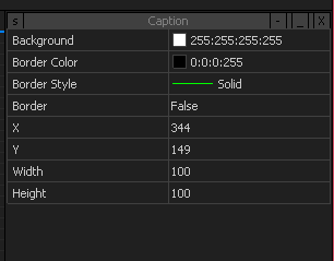
HMI Designer

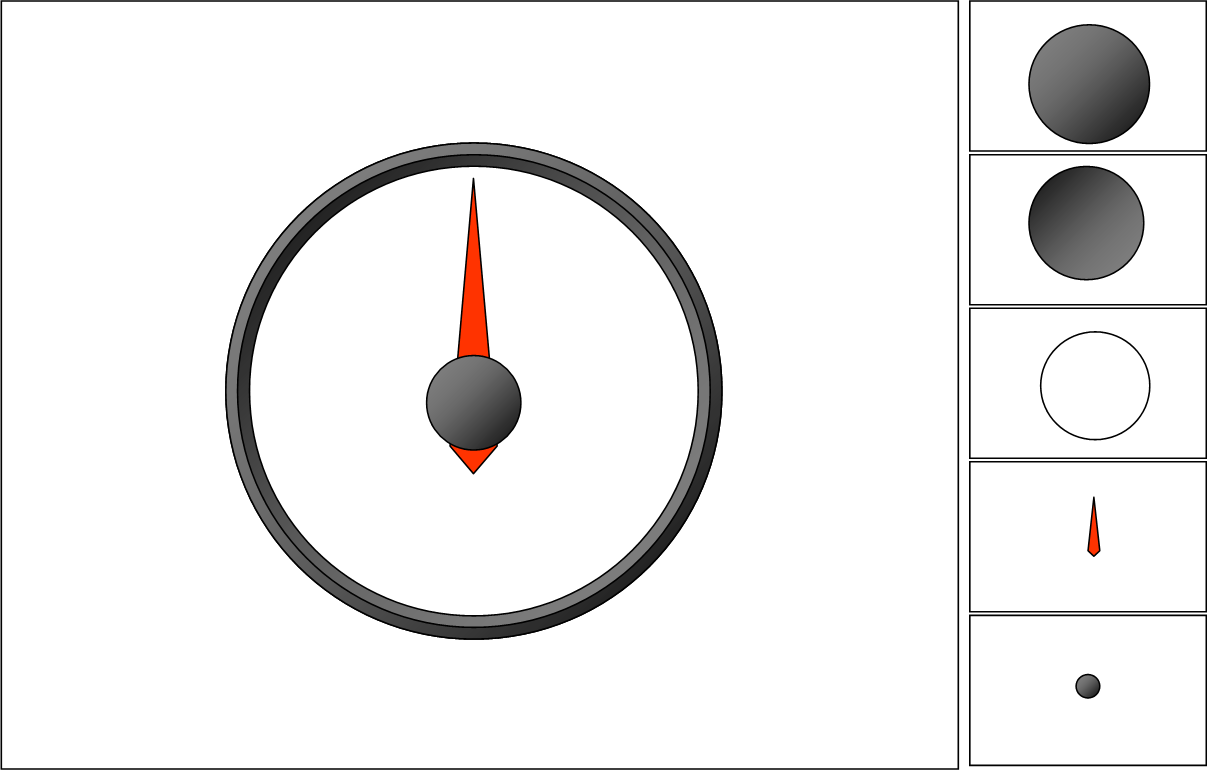
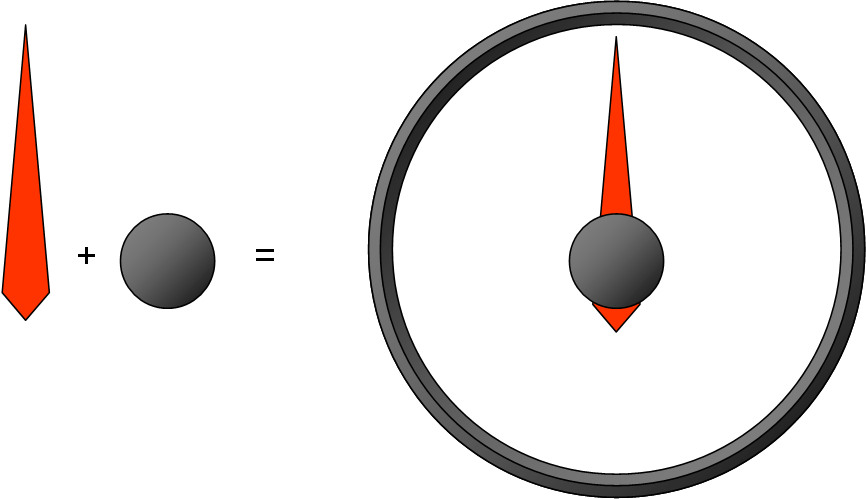
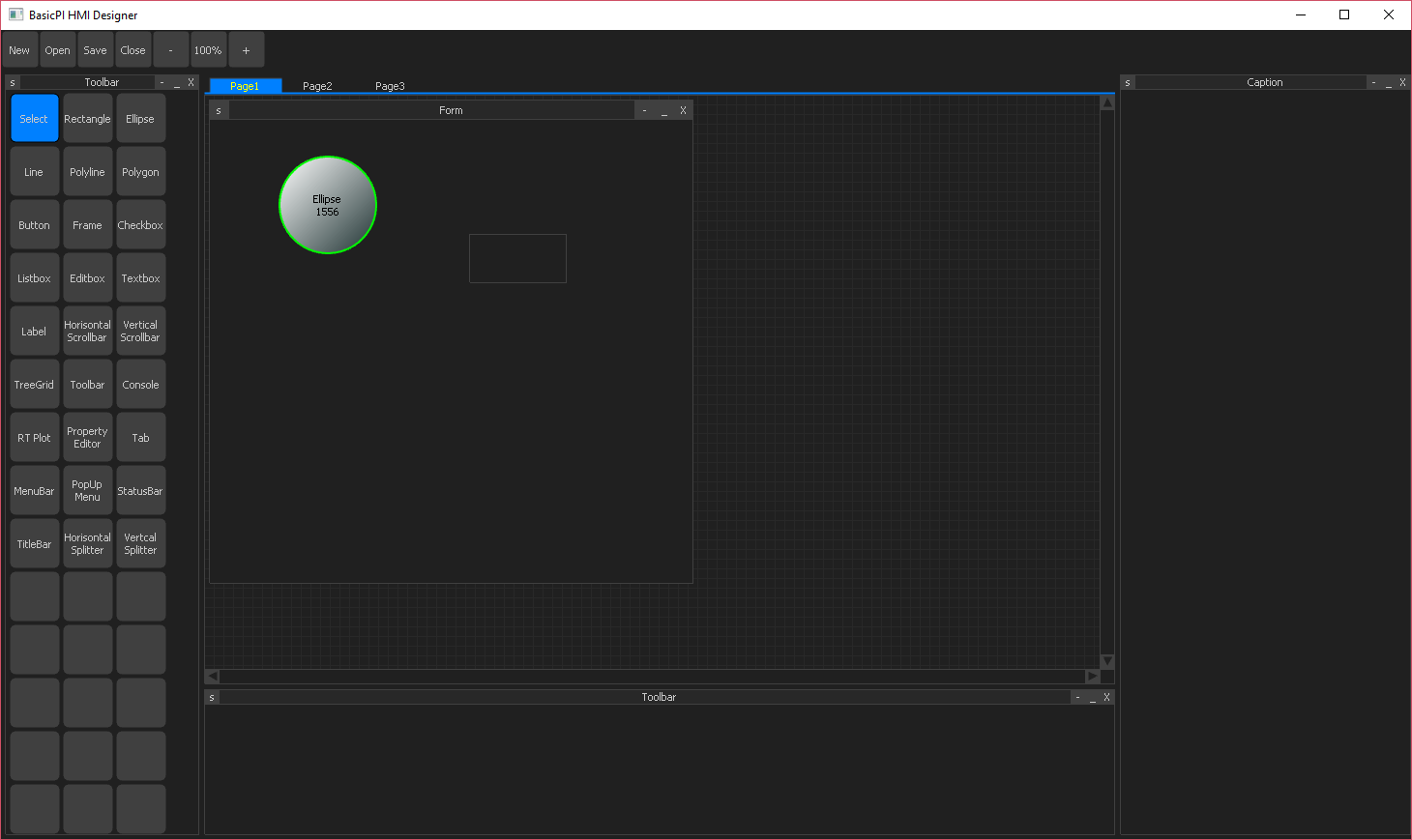
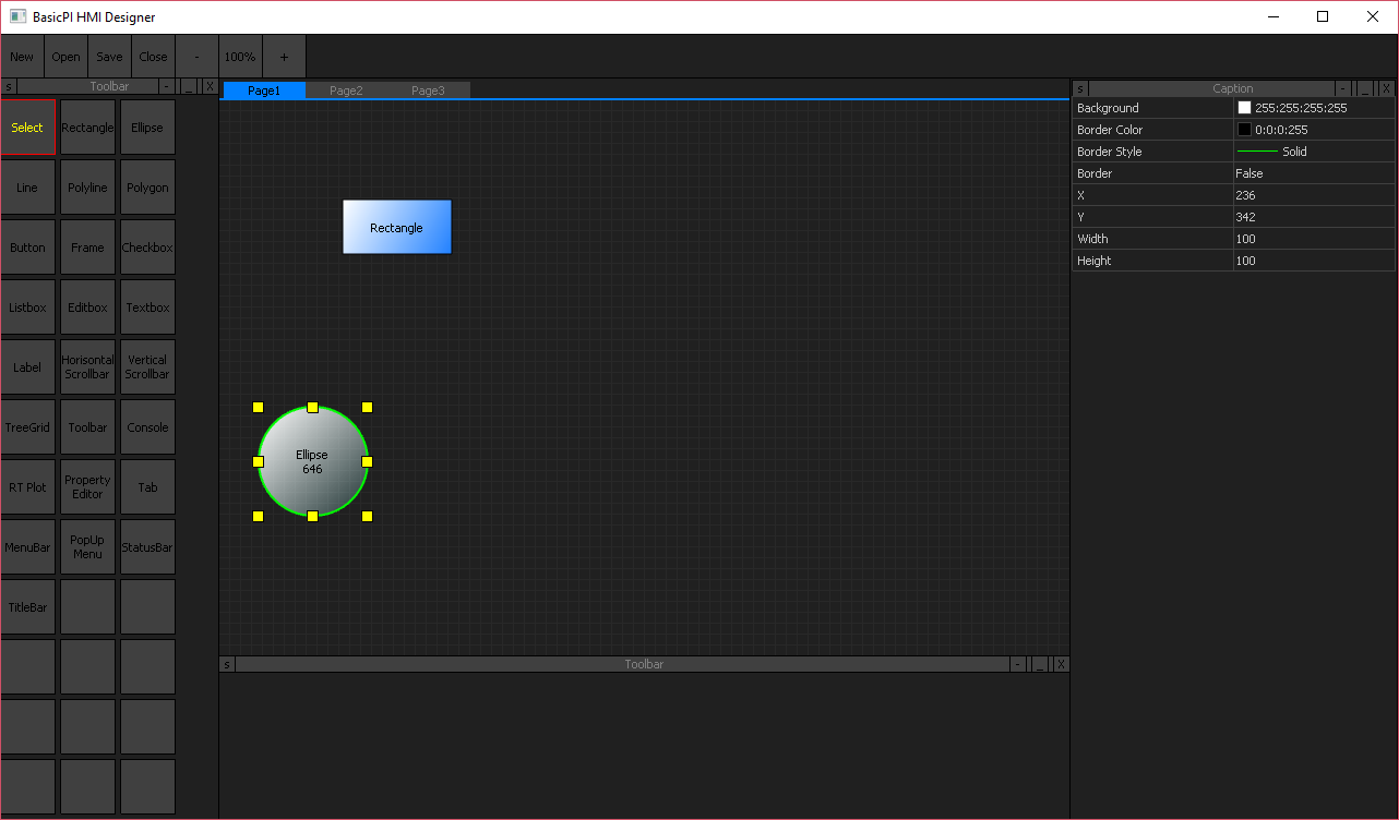
One of the applications I want to create is a “HMI Designer”. This is technically very easy as I have done similar applications before. What I will do is to create a graphical application that can design square objects on a form. Each object will have a name that we can use for IO through a serial line. To make the designer a bit more WYSIWYG we animate the objects as if they where “furniture” like Text Edit, Graphic Plot, Grid, Button etc. Each object will have a list of properties that are set/get design and run-time. The result is stored as an XML file and executed by a “HMI Browser”, a special application that download the XML and interact with the system.

This way we can design config HMI’s stored in the embedded devices as XML files and we only need to re-create the HMI Browser to support HMI on Windows, Linux, OSX, Android etc. The concept is not so unlike a Web Browser with the exception that the server here can be small embedded system in a closed loop. Nextion are selling displays build on a similar concept, so in time we can do our own embedded graphics displays as well. I do however want to do tings a bit different from Nextion.

One of the differences is usage of Plain as “scripting” language and interfacing using easyIPC and RSX as well as Ethernet/Wifi. The other difference is that I want a significantly larger object library and take advantage of GPU’s on Raspberry PI etc. I also want this to be a portable software package, not locked to proprietary hardware.

The most important difference is however system thinking. I want HMI Designer & HMI Browser to be building blocks in the CASE (Computer Aided Software Engineering) Tool I want to create on top of Plain. For now we will use Plain and the HMI Designer, but I do plan a fully graphical programming concept later.

As mentioned before with my Plain blogs I want to evolve the way we do software based system development. The network I build here have plenty of fun for C programmers and electronic hobbyists, but we need to create infrastructure and tools enabling this for non-specialists.

PLC/Home Automation HMI

I have been thinking a bit about creating a stand-alone HMI component. Basically a terminal with a touch display and optional keyboard, mouse and customized input equipment. The key principle would be that we use a Ethernet/RSX as bacbone for data traffic, while the HMI takes care of graphics, input etc.

This is just some random GIF I found on the net, but an HMI app could consist of a set of standard components where layout is controlled by XML files that are uploaded from the device. Communication could be Ethernet/RSX. Equiped with a Plain VM this could be an interesting concept where HMI logic is executed on the HMI unit and only events/data transferred to/from the rest of the system.

Making the app above might seem complicated, but it’s nothing I have not done before from scratch in C/C++. I am thinking more and more about creating a standard HMI app in Qt since that can run on Windows, Linux, Android, OsX etc. I need to check around for options.

<—->

Since we are talking about a network of stand-alone units we could create a full control center as well.

MicroPLC Backbone 3D

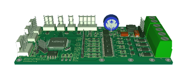
The latest version of the backbone bus. It is only 10cm long and with max 8 boards. Connectors are 2 x RSX, 5V PSU, and Actuator PSU’s. On the right side is jumpers and resistors for RS-485 terminator and bias.

The backbone’s can be connected in many ways simply by connecting RSX1 to RSX1 and mount the boards in any way you want. They can easily scale up from a single card to a large multiple backbone system. 32 devices can easily be directly connected, but using an active RSX switch you can scale much higher.

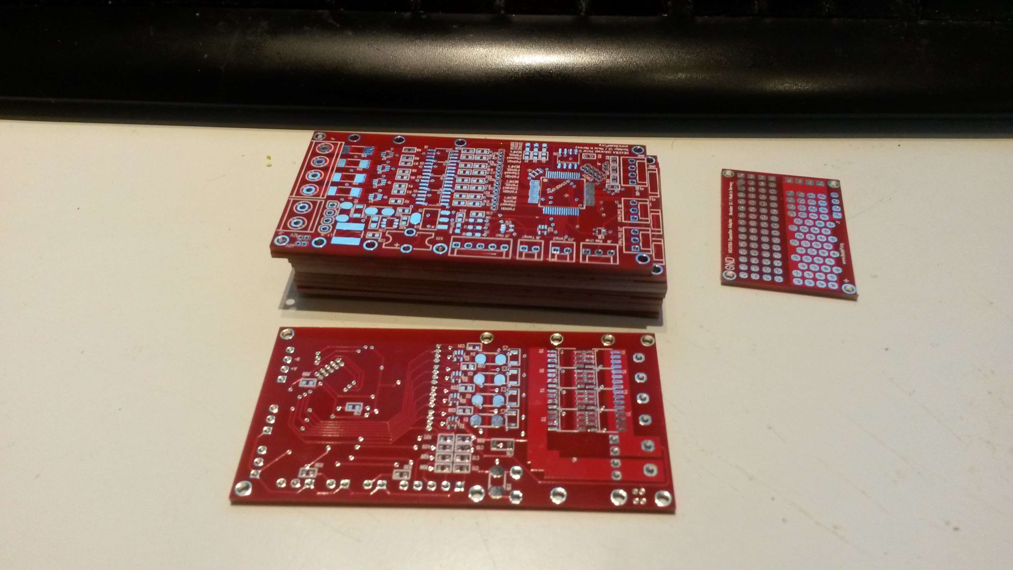
I think I have reached a point where I want to order PCB’s and get going. In this case I want to start with the Backbone, CCM and 3xRSX modules. I need to modify the SWD on the Servo Module + the main purpose with the Servo was actually to test the design. The Servo module have doen it’s job as it forced an important change on the backbone.

I also need to start on the 3D for the fittings and see if I can manage to print those with a 3D printer.

The RSX connectors on the backbone are high speed designed for very short range, but we can also interconnect using 3xRSX modules. I do however still need the RSX Switch with power for sensors, so I will push 2 more modules.

  • The active RSX switch.
  • An upgrade of my preious RSX Sensor (Temperature, humidity, light, distance).

I actually have a few RSX devices in rev 1 that need an update so we can start making a system consisting of sensors and actuators. One step at the time.

CubeMX

This picture is from CubeMX, just a few clicks and I have assigned 6 x UART’s, 3xSPI ports, crystal, SWD + added USB – the IO capabilities on the F405 never stop to amaze me + you gotta love CubeMX. Be a bit on your watch because not every possibility is available through CubeMX. Another tool I like is the 3D Paint version in Windows.

This is for the RS-X Switch.

Active RS485 Switch

I still got a few components to make\upgrade before I have a full Home Automation network. The CCM and RSX module allows me to create a central, but I need sensors and I need to feed the sensors power. One solution to this is to create an active RSX Switch with power output on each network.

The RS-X Switch as drawn here will take 2 x Ethernet or 2 x RS-X (M1 & M2) input and provide 4 x RS-X output with power. Each of RS-X E1,E2,E3 & E4 can be switched on/off separately and be used for networks or 1:1 with sensors/actuators.

The functionality in the switch is simple message switching. The idea of having 2 x Ethernet and 2 x RS-X Input is redundancy, but I realise this might be a bit tight to achieve so will see what pins & space I have available.

This module will also be a great RS485 Hub used stand-alone.

3 port Galvanic RS-X Module

3D of a 3-port RS485 GW. This actually have 5 RS485 (or RS-X). 2 on the backbone bus running high speed, and 3 isolated with lower speeds in front. These can be used Standard RS485, RSX or even Profibus/485.

The MCU is actually capable of running 3 port Profibus using UART’s saving the need for specialised hardware.

This module do not have the Raspberry PI Zero W add-on option. The reason is because the connector would conflict with the isolation area.

16 x Servo PLC Module

Added 2 coils on the 16 x Servo Module as well. On this I have plenty of space. I should have moved the MCU a bit down, but I will leave it for now.

This module provide output only, meaning it can not do generic IO as my previous 32xServo/IO could. The limitator is the opto couplers providing a full galvanic isolation.  It can still do digital output and low frequency PWM (< 100Khz) in addition to Servo signals.

Servo PSU is selectable from 5, 12 & 24V by jumper. Signal is also selectable from 5, 12 & 24V by Jumpers. The MCU 5V is separate from the Signal/Servo 5V etc.

It is also has a 4 pin HMI – the same as on the CCM board. I simply did not see any point in removing it + might be cool for demo/testing.

Doing 16 channel Servo on a STM32F405RG is well, the reason I use a M4 is the speed of the backbone bus.

CCM/PLC Module PSU Coils

Not very exiting – just added the 3 extra 15uH coil options I mentioned earlier on the back. As mentioned these are added because I suspect I need them to separate 5V PSU to different high frequency modules. The issue, as we learned earlier is that these freuencies interact. The coils here simply let 5V through but stop higher frequencies – it cost me little to just add the space for these on the back side.

I have a weird package error on the 25 Mhz crystal that I need to check, otherwise this is ready to go.

Also starting to use “CCM” (Communication Central Module) as name on this because it contains  Ethernet, GSM, GPRS, GPS, WIFI, Bluetooth,  USB++

PLC Modules

I updated the module list again – don’t worry – this will not be the last change here.

CCM (Communication Central Module) is the new name for the combined Ethernet, Wifi, Bluetooth, GSM/GPRS, GPS, RPI Module. I packed so much into this that it covered 3 planned modules.

Servo Controller Module was illustrated earlier.

I need to work on PSU/Battery.

3 x RS-X Module comping up.

8 x Analogue Input Module coming up.

PWM Output Module coming up.

Digital Input Module coming up.

DC/Stepper Controlles – we probably talk several modules here.

Sound I/O – now this becomes interesting. We have so far talked about a PLC that control robotics, but we could easily talk about a system that also does sound processing… I am very, very thin on analogue electronics, but some interesting options here.