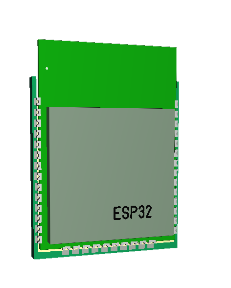
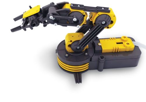
 I bought this robot arm a few years back for educational purposes. It’s great fun, but a bit limited in what it can do. The robot consist of 5 DC motors, but no sensors indicating position, so it is basically remote operated with no option for automation. I did create a RPI Hat dedicated for this one, but even that require a RPI that add to it’s size. ESP32 is so much neater as it replaces both RPI and the IO MCU.
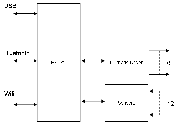
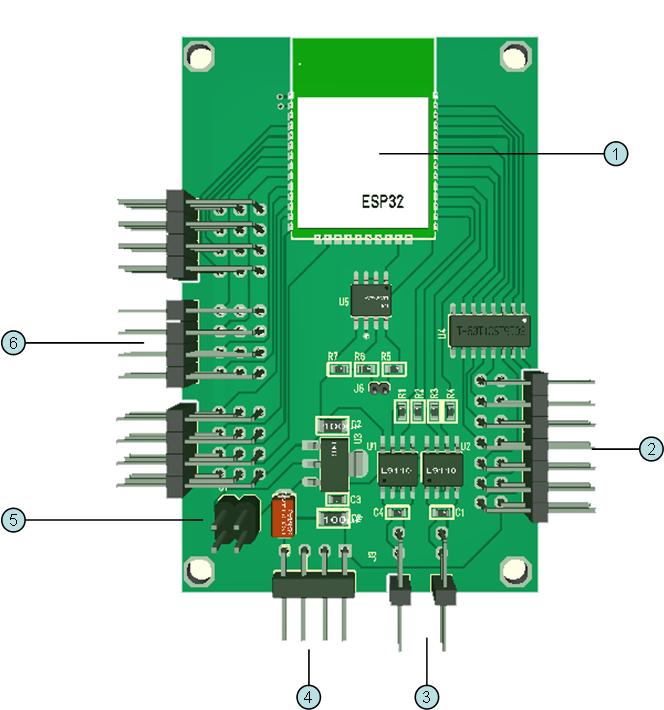
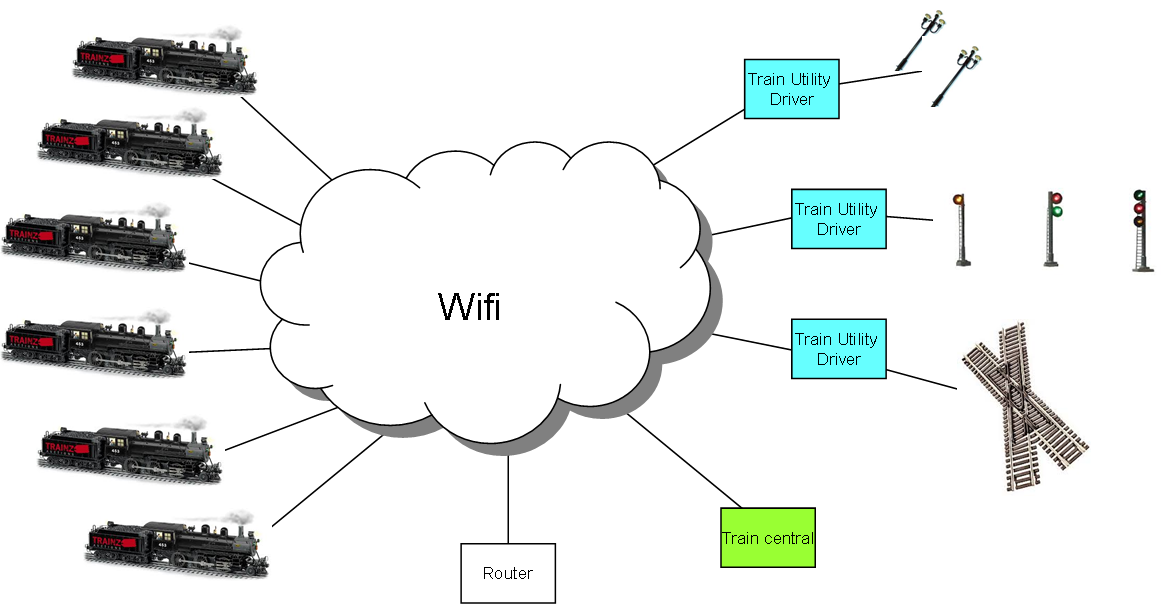
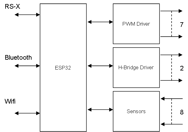
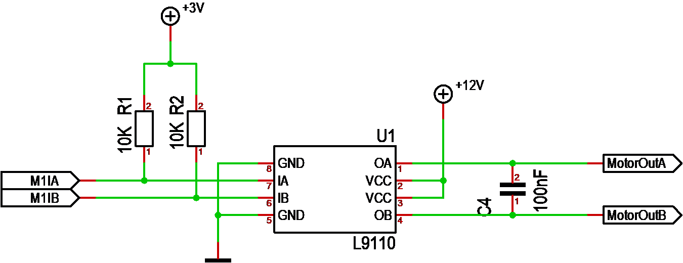
This block diagram is based on the Train Utility Driver as I just remove the PWM signals and increase the number of H-Bridges to 5+ 1/2.
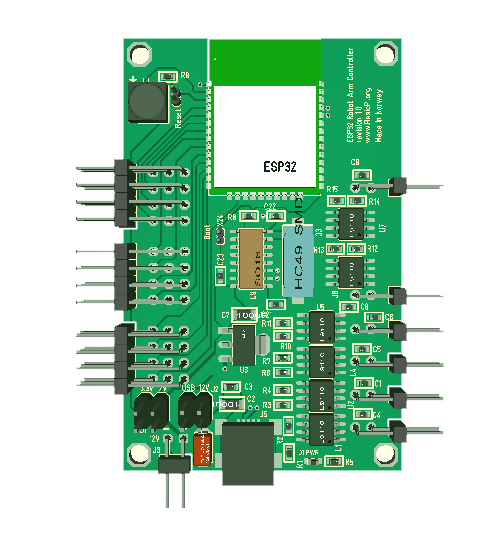
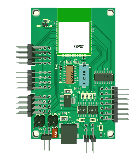
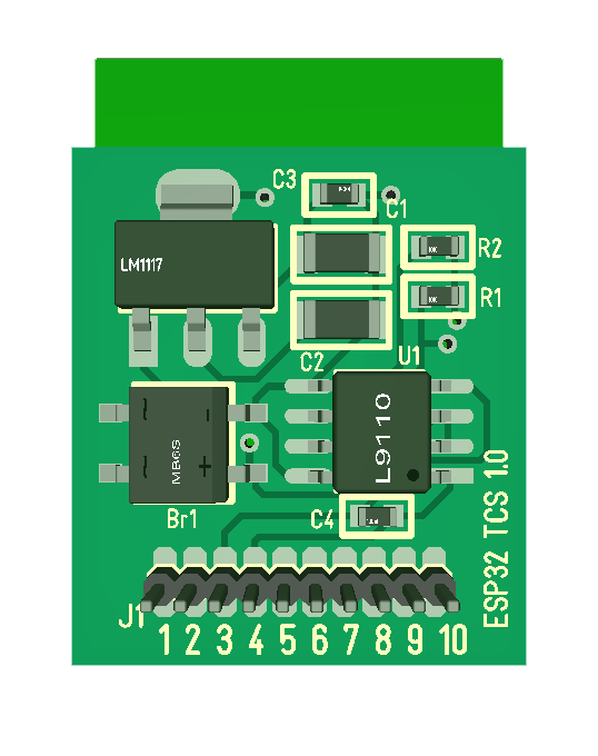
If you compare with the Train Utility Controller you will see that this have 6 H-Bridges on right side. It actually is 5 H-Bridges and 1 PWM signal. The illustration show right angle connectors, but this will mostly use straight connectors.
That said I want to wait a bit with this one until I get the others back and get a bit more experience with ESP32.