Drawing User Controls – No Coding

This is just an idea, but C++ gauge code is basically a set of layers on top of each other. The idea for user controls is to let the user draw separate drawings – this could be visualized as a text tree, but I consider it as a graphics list/tree. The user can then link a drawing to rotate, zoom scroll based on an input value to create value based animation.

This also questions if I should bother with build in gauges at all – an xml based repository can provide the user with gauges that he can use “as is” or copy&modify. It also opens for others to create add-in libraries, which in previous tools have proven to be a key asset.

Drawing Gauges – The Needle

Using the clock bewel from earlier I want to add a needle (polygon) and a cap as indicated above. I now want to rotate the needle based on an input value.

Rotation can be done by doing the math yourselves and drawing graphics. The drawback with this is that you use the CPU, so what we will do is to use the build in transform that can rotate, zoom and scroll using the GPU.

So in simple words we just assosiace the rotation angle with an input value and a scale. In this case we rotate the needle layer of our drawing. The advantage of doing this is that we could also rotate the scale (not shown) or use a combination of zooming, rotation and scrolling to animate a value.

Drawing Gauges – The Bewel

The circle above is a “Bewel” often used around a classic clock gauge. Drawing this is straight forward as you draw 3 circles on top of eachother as illustrated below.

I will create some build in gauges, but I think the most important gauge is the one you create yourselves. So I will leave you tools to create your own animated gauges and use them as if they where build in – no coding needed!

HMI Designer

Getting there. I am actually starting to see the end of initial framework tasks, so we can soon move on to more interesting and visual content. It’s a lot of work to be honest…

I am happy with using Qt as base. It allows me to write C++ which is optional for this task due to performance and Qt have done a great job integrating OpenGL. So far you only see a 2D content, but you will see the difference as we start with 3D gauges at some point. I have done this without Qt both on MFC/VC++, C#, C++/GDI++ and Lazarus, so I know what I talk about stating that Qt carry it’s weight around on graphics.

Property Editor

The Property Editor is a control that allow a group of “properties” (read data variables) to be edited. Rather than making specialized screens you simply list the variables in a TreeGrid and allow each item to be edited using a specialized editor for the data type. It is a quick way of creating an editor and quite common in modern programming environments.

This editor is quite a lot of work since it also require a lot of other editors to be created. You will probably notice that I am starting with the dark theme with flat controls found in Visual Studio & Windows 10. Actually the theme and style is custom and neither Windows, Linux or OSX. The reason is because most applications today want a recognizable company style on their applications that stay the same regardless of what device or platform you use. I start with my own preference.

A custom style means that you need to create everything from scratch because you need to control every color used. I did this by modifying Windows controls earlier and it was basically more work and less freedom than what I do now. It is a lot more work than just using the build in Windows controls, but it is worth it because the result is a high performance graphics HMI with presentation graphics capable to compete with web applications.

The Property Editor is used to edit objects on the design screen, but is also a component that can be used in user applications. All colors & style setting are programmable per component, but default values are fetched from a theme database. You will be able to create your own themes as well as select pre-made themes.

HMI – User Controls

I still have some work to do on the basic drawing/HMI engine, but will soon be focusing entirely on what I call “furniture” as in pre-made controls we can use. I will create some fancy, build in controls, but the most important one is a “User Control” enabling us to create custom controls. Now-keep in mind that the entire HMI is specified in XML format and loaded as we start the HMI Browser, so a custom control will need to be loaded as part of this. For the Designer, we would like to have a library that is made available, but only those that are used to be included in the final XML.

The User Control itself needs to be built from other controls and by adding colors, scaling, rotation etc to create a new control. This means our user control will be a list of build-in controls where we create our own, new interface. As input values can transform to position or rotation we should be able to create most controls these ways.

To enhance our customization capabilities, we have Polygon and Plain. I don’t want to dig into the same security problems as ordinary browsers, so the Plain VM will only have access to HMI Browser, not any of the host OS capabilities. If we need the later we will have other options for that.

Actuator-/Sensor-Design

Making an Actuator- or Sensor- Control System require a little bit of software. It is many ways of doing this, but I always tend to use a pre-tested design containing of 4 main parts:

Communication is always required as we either take instructions or send data/progress to another control unit. This is usually also the largest and most complex software component needed. Many designs will implement a communication protocol and the app as just an extension to this. Myself I use an Object Dictionary.

Object Dictionary is a generic database interfacing between multiple applications using the same data. In its simplest form it is nothing but an array between data communication and sensors/actuators mapping data. A more sophisticated feature often needed is data integrity. As communication is capable of writing partly data we need a mechanism to commit or rollback so that the application only see consistent data sets. Another feature is the capability for persistent storage on selected variables or straight forward database queries.

The various user modules are Actuator(s), Sensor(s) and various other modules either using or providing data.

The last bulk of code is the infrastructure with RTOS and utilities.

The main issue here is that this design only need a map of data in the object dictionary, the right modules added and it adapts to any actuator sensor design.

Universal Motor Controller – Actuator Control System

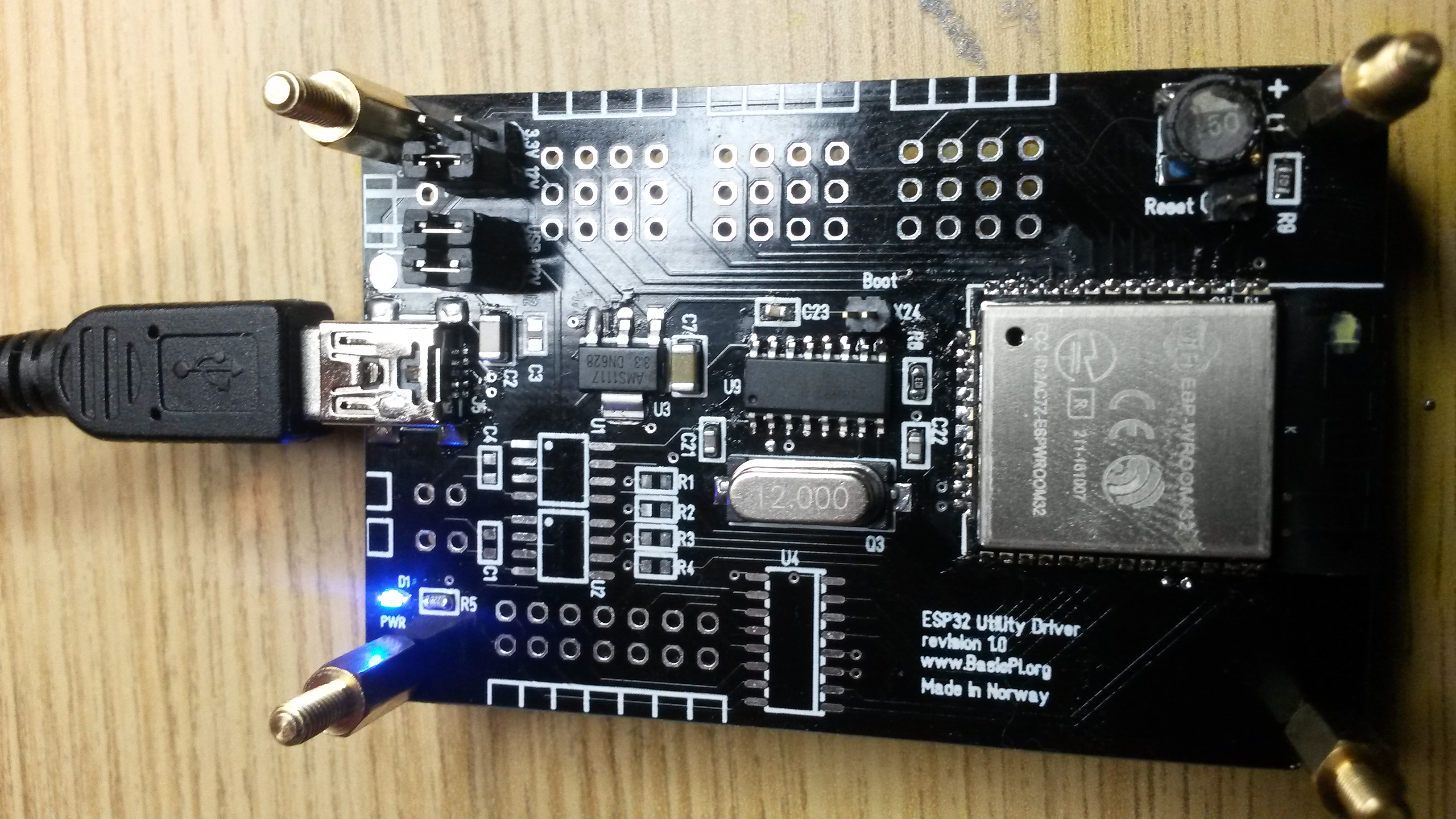
I have a few electronic designs that annoy me simply because I lack time to work on them. The reason is simply to much happening in RL with projects (have to pay the bills) + focus on Software. This one is the worst. It is actually one of my most advanced designs and a very capable Actuator Control System.

I started this partly because I wanted to make my own 3-phase motor controller. But, as I did the design I also added a 4th Half-Bridge, Hall Sensors, Temperature Sensors, End point Sensors, Resolver input as well as the RS-X port. It is much better 3-phase motor controllers than this around, but that’s the point – this is not a motor controller it is a scalable Actuator Control System.

I

I blogged a lot about MicroPLC/Home Automation lately, and this design fit’s right into this scheme. We can’t use long wires with actuators involved as they need to be close to the objects they control (high currents). A centralized PLC design is not optional in a home that actually need distributed unit’s like this.

I will get down to it, but for now I want to focus on getting the HMI running. One of the first projects will be test applications for these devices.

The concept I will use is that the HMI Browser contact this device and upload the HMI. So all you install on the desktop, phone or tablet is a HMI Browser. This is similar to things you know from classic Web Browsers and HTML5, but the main difference is that we operate on a closed, industrial network consisting of a combination of technologies.

One aspect of easyIPC that I have not mentioned is that you have a set of HMI & devices that actually are a closed, industrial loop. It is not connected or available to internet or the outside world unless you want it to. Neither will you be able to connect any phone or tablet if it is on Wifi – the devices will need to be enabled from inside (white listed).

HMI – Image Editor

One of the tools I need to add for HMI Designer is a bitmap/Image editor. A simple bitmap editor is easy to create just using an array of 32×32 positions and allow the user to set colors to them.

One technique could be to allow an image to be drawn in full size and then converted to various sizes like this example based on MSPaint.

Doing this using my existing diagram editor would be straight forward, but I would also like the capability to import various formats.

The primary usage is bitmap/tools in HMI Designer itself, but this is also an important part of any HMI designer. Doing this in a vector based drawing tool lgive the advantage of full scalability, so combining this with a controlled capability to create faste, fixed bitmap’s as output might be an idea.