5A reached on Motor Driver

Not so much to write home about, but adding the heat sink back on I turned it up to 5A on a single channel – no heat noticed. My new loads do their job consuming some 100W, but my 5A PSU reached it’s limit. This was 20% duty cycle, so actual phase current was 25A. I tried a 2nd channel, but I struggle to find HEXFET’s that work so I am looking forward to get a proper batch in a few weeks time.

This leaves the challenge of the current sensor. I will try a few more of the INA210 and see if I get anything out of them. I will also remove the low pass filter I added after the amplifier to test. One of the challenges with INA210 is that this limits the driver to 26V,  At 30V the MOSFET’s become the limit, so this is basically a 24V design.

As for the MOSFET’s. These are rated 30V @ 17A and seems to cost ca 0.8 USD each. At that price I can as well change to the ones that is rated 30A. They cost a little more, but will use up ca half the heat dissipation.

3A – no heat sink

I have removed the heat-sink on the pcture above and is testing on the one good channel I had left. Just using my fingers on the MOSFET’s I get to 3A without heat-sink. This is very promissing and indicate that I have suffered a bit bad numbers from bad MOSFET’s.

Bad IRF7862 MOSFET Lot

Update : 13 of 50 MOSFET’s might be ok after testing!

I purchased 50 x IRF7862 MOSFET’s from Asia through AliExpress and while I usually am happy with what I buy here it happens that I get screwed by non-honest sellers. What some of them do is to pick rejected chips from the factory and sell them. These MOSFET’s arrived in a plastic bag, not in original packing so I should have rejected them due to that alone, but I was obviously not on my watch back in 2016.

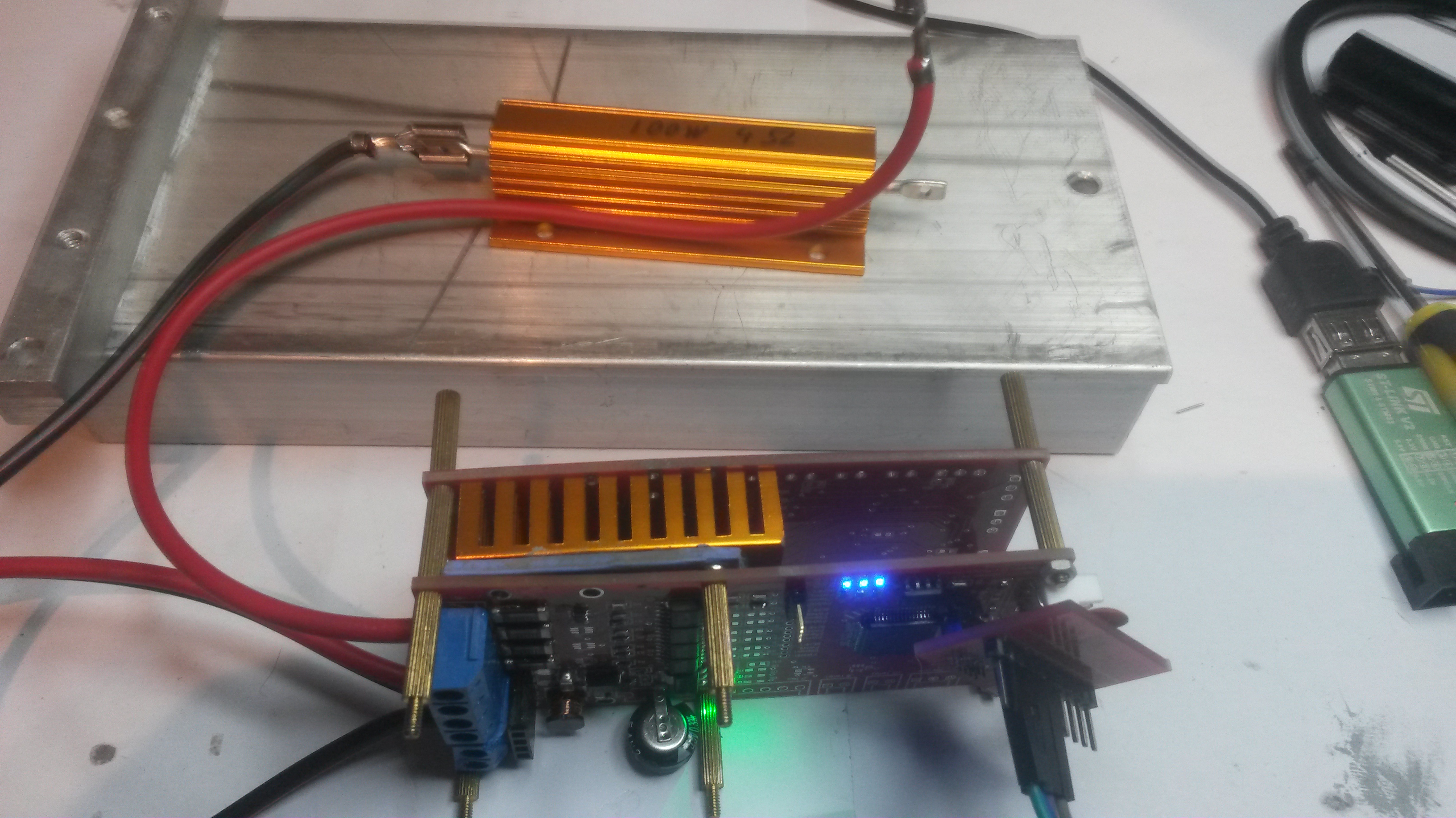
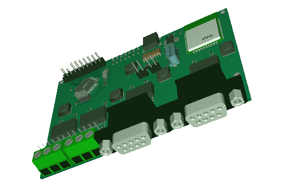
These was for my motor driver and are supposed to have 3.3mOhm internal resistance as well as a very fast switch time. I was therefore a bit surprised that they generated so much heat as they did and that so many of them was destroyed so fast. After I destroyed my test channel yesterday I soldered on a new one and realized it was non-working as well. I tested the lot manually and had to reject 6 of them. Soldering on 2 new ones I still discovered that they did not work. Scoping the gate I even see they distort the gate signal, so 2 new ones and gate signals are ok, but output (no load) is crap.

This lot was bought back in November 2016 and costed 16.45 USD (0,329 USD each). Well, this is what you must expect from time to time buying samples from AliExpress. I believe this is the 2nd time I had bad luck like this. The alternative to buy all components from distributors would be far to expensive for a hobbyist scheme.

What I will do next is to test manually and see if I can find a few that hold ca spec. This is easy as you just use the PSU, connect on each end with 10V over the MOSFET, put the current limit to < 1A and bring the gate to 10V. This will bring the PSU down so I will not get 3.3mOhm as Voltage will be to low, but it will indicate if they work at all.

I must admit I thought these MOSFET’s snapped a bit fast, so I had actually planned to replace them With IRFH5300, but I need a New PCB layout for these. IRFH5300 is rated to 30A. I don’t expect to get 30A out of this design, but they have a much lover resistance and I should get 15A out with far less heat. Luckily the IRFH5300 was from a profiled seller and arrived in original package.

Returning to IRF7862 – what I will buy 20x from different sellers and pick a profiled seller this time. I also see that price range is huge + a good indication that something is wrong is if you don’t receive chips in original package – these came in a plastic bag! Prices range from 0.28 each to 0.90 each. I picked IRF7862 due to it’s low cost, but if I have to pay 0.90 each I can as well use IRFE5300.

Motor Controller Testing

This picture show my latest test upset. I am still only testing a single PWM channel on MC4X15A, but it has caused a few Challenges.

I finally got hold of 100W resistors that can sustain heavier load and using a 4 Ohm 100W I can continue my testing without being concerned about the load melting the solder tin as my previous one did. I expect the load to heat up as I am throwing out 40-100W on it. I did however not expect the MOSFET’s to heat up this fast.

I tested with 28V for a while getting a nice 1.2A out which is OK since I had low PWM duty. I connected a DC motor with the 2 Ohm load in series and it instantly span up in 80ich Watt and maxed out the PSU on 3A. I assume I broke the MOSFET at this point due to spikes as I was running without capacitance/protection on the PSU feed.

Gate drivers and MCU are ok, so I assume the supercap/diodes did it’s job and protected the MCU, but I fear I might have 8 x broken MOSFET’s – well, will find out tomorrow! My own fault for attaching a motor without adding the capacitor/diodes on the PSU.

New SWD Connector

One of the generic changes I have considered for some time is to replace my 2×5 pin SWD connector with a 1×5 pin Micro JST connector. These connectors use 1.27 pitch and you get plenty of ready made cables. Firstly I only use 1×5 pin anyway and usually find other solutions for debug UART. But, most important is that connecting the adaptor directly to the board is not always convenient in tight places. A JST connector with a cable will fit more smoothly and allow me more freedom.


The picture don’t really show how small these connectors are, but you find plenty of them searching for “micro jst”. I plan to modify the existing adaptor and use this cable between the adaptor and the PCB Board so that I don’t need to adapt it directly.

Pin layout is still the same except for the New 3.3V:

  • 3.3V (new on 6-pin)
  • NRST
  • SWDIO
  • GND
  • SWCLK
  • BOOT

I assume I have to make it 6-pin and add 3.3V as I want Reset and Boot jumpers/switches on the next adapter board. Basically I don’t really need to do anything as I can use this directly as a drop in replacement on the existing Connectors (1×5-pin).

Also, I often have lack of connector space on my designs, so I am tempted to use these several places where the connector size is an issue!

CAN-USB Adapters

I am adding 2 CAN/USB Adaptors. The upper one is not galvanic isolated while the lower one is 2cm longer and uses ADM3053 which also makes the board ca 5-8.- USD more expensive. The MCU is STM32F105RB and the USB is full host or Device capable. The SN65HVD233 based one have a few Control functions ADM3053 does not have, but the Boards are basically identical.

ADM3053 Error

I just realized that ADM3053 is NOT a 3.3V device. It says 5V or 3.3V on VIO, but VCC requires 5V. The schematics I have used is also wrong as it does not feed power to VIO at all. The example on the datasheet is very misleading in this case. Looking at ADM2583 that I uses for RS485 this is all sorted – it actually IS a 3.3V device. This is a bit annoying because it means I need to maintain both 3.3V and 5V since 3.3V is needed elsewhere.


CAN/RS485-Wifi Adapter

I have mentioned that I need a dual CAN to Wifi Adapter as well as a dual RS485 to Wifi adapter, so I decided to make one that can serve both needs. This uses ESP32 to get Wifi, USB and Bluetooth and a STM32F405RG to get dual CAN as well as dual 10Mbps RS485 – all galvanic isolated.

The CAN Adapter is for professional usage, while the RS485 is partly as an adapter to my PLC system as well as a Wifi adapter to my DPS5005 & DPS5020 based PSU’s.

Layout on this was a bit tricky due to the size of the 9-pin D-Sub connectors and I am not done, but the current draft look very promising. Hopefully I will have this in rev 1.0 around October. Size is 100 x 70mm.

I actually started end partly developed a different adapter last time I needed CAN. I never finished that design, but much of the design is tested, verified and reused here. The only missing part is wired Ethernet.

ESP32 Oscilloscope & Logic Analyzer

Most of my Oscilloscope & Logic Analyzer needs are on frequencies below 1Mhz, and ESP32 have 16 12-bit ADC channels, so it would not take much to create a 16 channel low frequency Oscilloscope/Logic analyzer. This is why I bought a ESP32-WROVER dev kit. Wrover have 4Mb SRAM as well as all the features of ESP32.

Max sampling rate on ESP32 is 2Msps. The details here are not well documented, but if we assume a minimum of 10 samples per Hz we should be able to sample frequencies up to 200Khz. Even more interesting is that ESP32 contains support of programmable Gain through it’s logic pad’s. Again I must state that my knowledge in this area is limited and so it doc on the subject, so I need to experiment and see what I can achieve.

The good thing is that all I need is a breadboard and a kit costing 10.- USD to test this out. No guarantees, but it will regardless be interesting playing with the ESP32 ADC channels.

INA210 – Current Sensing

These scope pictures are from MC4X15A measured at 0,5A and 0,7A on the PSU. The yellow is just the pulse trigger, the cyan is the actual CSense on ch1. The cyan line is the CSense. CSense seemed to increase in average as I increased voltage. Phase current is larger, so a 200mV signal might be ok-ich – I have not done the math exact – 0.5A is ca 0,1V and looking at the scope average 64mV that is 0,32A while 77mV is 0,39A – the math don’t add up so I am not sure what I am looking at.

Measuring the shunt with a multimeter I get 0,3mV which indicate 0,3A while the PSU indicate 0,5A – Increasing to 0,7A I measure 0,5mV which calculate to 0,5A – so the shunt seems to be “ok” with a 0,2A difference from PSU – but keep in mind that numbers are not exact here and it’s a difference between PSU current and phase current.

I have a filter AFTER INA210 that I will remove + I want to look at a non-amplified signal on CH2 to compare. I also need to sample and compute in SW with an actual ADC – I can only repeat that I am not convinced by INA210 yet. I will add proper load later so we can test higher currents. I did test 0.9A, but the scope pic did not convince me.