Motor Controller – Current Sensing

I don’t get much sense out from the INA210 at 0 – 2A. Firstly I realize that I use a far to large Shunt resistor. I use a 0.1R by mistake. 100mA would give 10mV that amplified with 200 should be 2V. At this size the Shunt become my weak point. At 3A it starts getting very warm as I dispose 0,9W and it is rated at 1W. I need to replace this, but I accidentally lack smaller shunt’s yet.

With 15A and 0.001R I should get 0,015V that amplified with 200 should be 3V. With a 12 bit ADC giving a range of 4096 I should in theory have a current sensitivity of ca 4mA (15A / 4096).

For now I need to wait on 0,001 shunts, but I will find a load that can support 0-150mA so I can test this range.

I want to test INA210 a bit more to see if I get any sense out of it, but it cost 50c and the tiny package makes it a pain to use. Using a 2 layer PCB I am also at a disadvantage regarding noise.

As for load testing… I am melting my load at 3A. I use 10 x 0,47Ohn @5W in series to create a 4,7 Ohm 50W resistor, but it get so hot that it melt the soldering tin on my home made load. I have mounted a 40x40x10mm Heat-Sink and the only component getting hot is my 0,1R Shunt. I can manage 10A out from my Lab PSU and that will have to do for now. But, I want to move load testing to a  different boards with only PWM driver Circuit before I continue. It is basically so much work to solder a full board that I don’t want to destroy this one. Have been replacing 5 x HEXFET’s so far as I tested without heat-sink. I can only sustain 1A without a heat-sink on. I need to do the math here as I expected more.

All in all – this design seems to work. It will be down to current sensing and finding an optimal heat-sink I think. But, I am currently only testing 3A and it’s a way up to 15A continuously yet – mostly stopped due to lack of test equipment as we speak.

Programmable Lab PSU

I fancied testing my MC4X15A motor controller as the driver for a PSU. The code is very simple as I bit-bang a PWM with 50% duty and use filter consisting of a 100uH coil and 1000uF capacitor.

The result was quite good. I did however notice some input ripple. As I also scoped the Lab PSU output I saw a much, much smaller of the same ripple. Replacing the cables the input ripple improved. What happens is that due to wire resistance we get a power drop as we start drawing current. The drop was actually 1V before I changed cable.

My home made little PSU actually worked quite well. I would have needed a better filter, but output ripple was not horrible and if I had put a decent driver and wiring it probably would have disappeared.

I used 100uH, but a real PSU would use something like 10uH to get a lower power drop in the filter. My motor controller hold it’s ground at 1A, but temperature on HEXFET’s started to rise at 1,2A. I need to work on cooling obviously.

MC4X15A – Motor Driver Testing

I am so far happy with the MC4X15A PWM channel with the exception of the current sensor. I have 3 more channels to solder up, so I will do the next without the low pass filter for comparison. I did not like the scope pictures, but will be interesting to see what I can do in software.

This picture illustrate some of the challenges involved in scoping. I am using a 2nd SWD adapter to get hold of the 4 pins so I can scope them while testing. As mentioned while I meade this I intend to destroy a few boards to learn the driver limits. I accidentally burned transistors with a shortcut, so will be interesting to see the limit as I add heatsink.

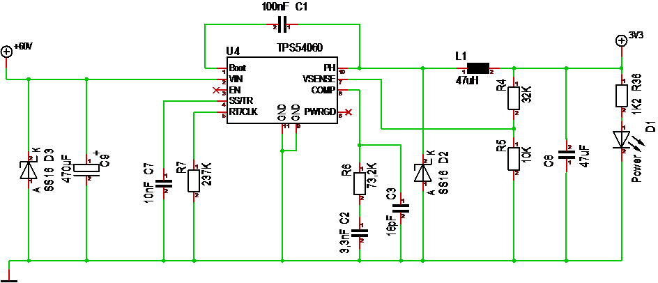
I am also running the MCU at 8Mhz yet. It will be interesting to see what happens as I increase frequency and things get more sensitive as I have a lot of noise at moment. The HEXFET’s have a 30V limit, so if the PSU noise is an issue I will replace the DC/DC with a 78M12. One thing that works well is the supercap. I am surprised of long it keeps the MCU ticking after power-cut and it should do wonders in absorbing spikes and protecting the 3.3V.

One of the next things I will do is to solder up a PWM channel on a separate board and burn it. This test is a bit tricky as I don’t have a Lab PSU to support the test yet.

3.3V Supercap

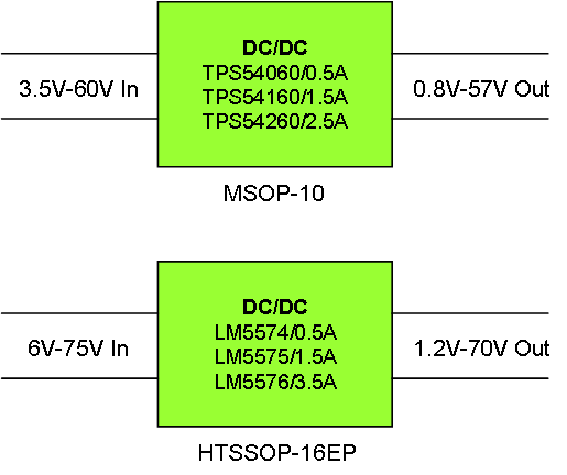
These are the two different PSU’s used on MC4X15A – notice the supercap X20. I mounted a 0.33F Supercap for the purpose of keeping the MCU alive during powercut’s + act as a spike absorber on 3.3V. I am impressed – the PWM cut instantly, but Led’s and MCU keeps going for several seconds.

INA210 Corrected

The first thing I noted was that my current readings went into negative voltage, so a bit research and I moved the ref pin 1 to ground – it seems to work better. I won’t know for sure before I activate the ADC and print readings. INA210 is supposed to have gain 200, but I fail to measure that with a multimeter. Lets see what the ADC says.

One thing I do see is noise – lots of it.

MC4X15A – Motor Controller – First Test

These two scope pictures stunned me before I realized the mistake that stunned me even more. The first picture show HEXFET Output in yellow, Logic High/Low Cyan and Purple and BEMF voltage in Blue. The upper picture is with no load and the 2nd is with a DC motor as load. Why do my High signal get disturbed ? Read on and get amused!

The answer baffled me. At first I was puzled by how weak the motor felt, but it was working and the controller with motor used 21mA – up to 40 if I held it. But, what was wrong? Looking at my test set-up I suddenly realized I was driving the motor directly from the STM32 High pin.

 STM32 delivers up to 40mA per pin and this motor worked on 3.3V 21mA or something. Connecting it correctly it felt like a formula 1 in comparison.

Half-Bridge Shortcut

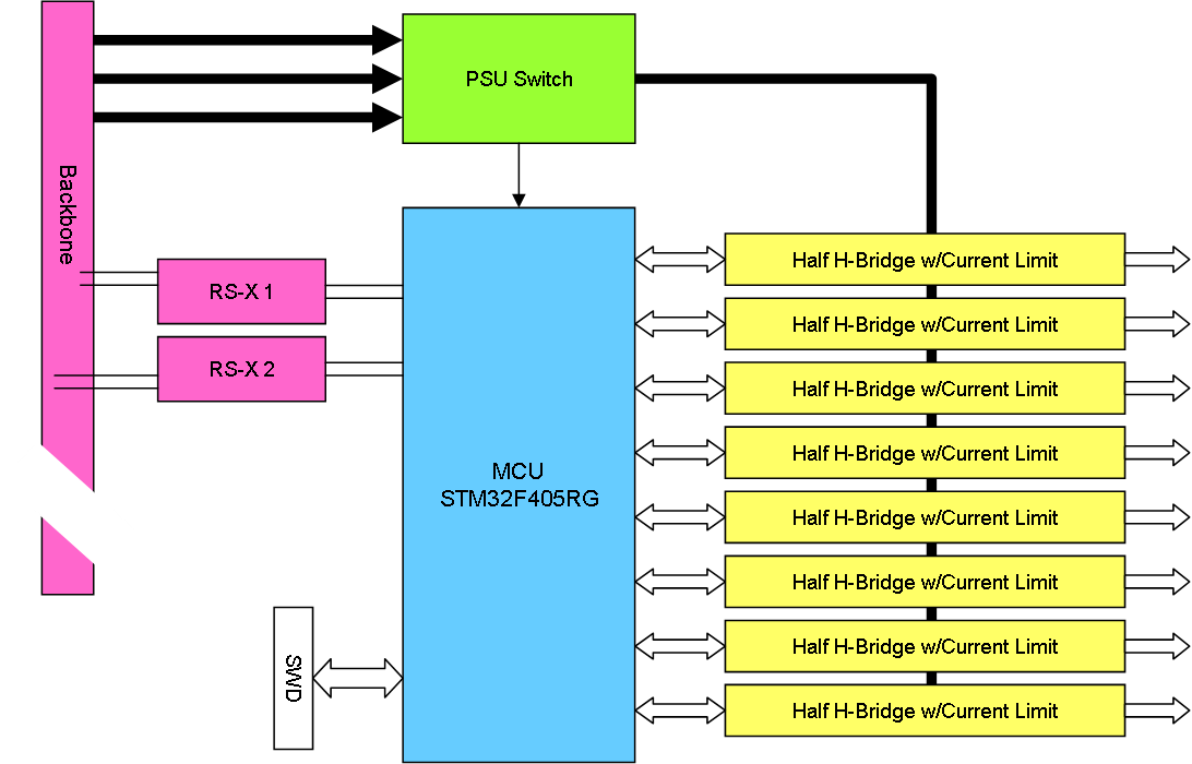
This schematics show the PWM driver stage of MC4X15A. IRF7862 is rated at 17-21A continuous current and pulses as high as 170A, but yesterday I took out two simply because I replaced IR2103 with IR2101 and did not realize that the later have no short-cut protection – so the MCU switched on both High and Low, dragging the PSU down. It was only ca 4A, but with no heat-sinks the SO8 packages will be exposed, so they snapped from overheating.

I planned on burning this board a bit, but not yet – I want to test if it works before I stress test it – lol. Well, new HEXFET’s – new try + I need to remove that IR2101S and get a IR2103S on.

Good news was that I could connect to 3.3V and things worked – it was only the HEXFET part that failed – no marks on the PCB or other Components.

INA210 Tagging

I wanted to share this picture of a INA210 through a microscope. The size of this component is ca the same as a 0603 Component with 6 pins. It is small, but soldering it is not the issue – this bugger have 6 pins and where is PIN 1? I assume it is top left on the current picture, but smallest component I ever have soldered and unclear tagging – yeah – how fun.

 I was a bit worried about soldering these for hand, but that seems to be ok with a hot air nozle as long as I can see between the legs and avoid short-cuts. This is a SC70 package it is 2/3 of SC23, and to be honest a 6-pin SC70 – the diodes did not feel so bad as they had 5 pins, but this was a struggle. I think I should consider an alternative solution, but lets see how well this Works first.