RPI Hub PCB Layout

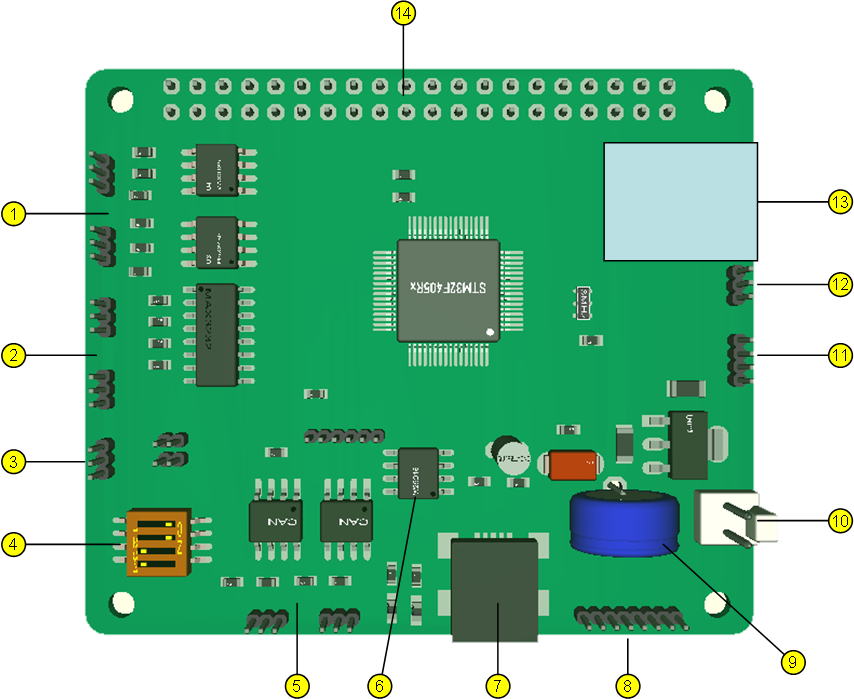
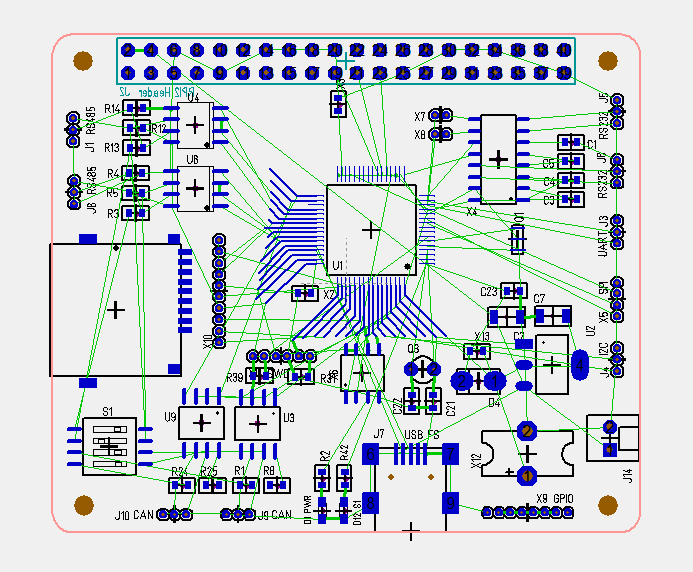
A bit different picture this time. This show the component layout and the green lines are the PCB lanes I need to make. I have added the package for the Micro SD Card holder, but I still only use 1.27 pitch headers for the Micro JST connectors. GPIO Header is not wired in schematics yet. The exercise here is to have as little crossing green lines as possible to make PCB layout smoother, but this starts to look promissing.

I added a 10 pin 1.27 connector for SD card. It gives me the option to use this as a 9 pin IO connector + the header make signals available on both sides.

I will start to upgrade my other RPI hat’s once this is done. I have a 32 port Servo controller + 8 port DC-motor controller, but I also want to move on with a 7 port stepper/PWM controller. Have them all as RPI-Hat’s, stand-alone USB or CANbus plug-in’s.

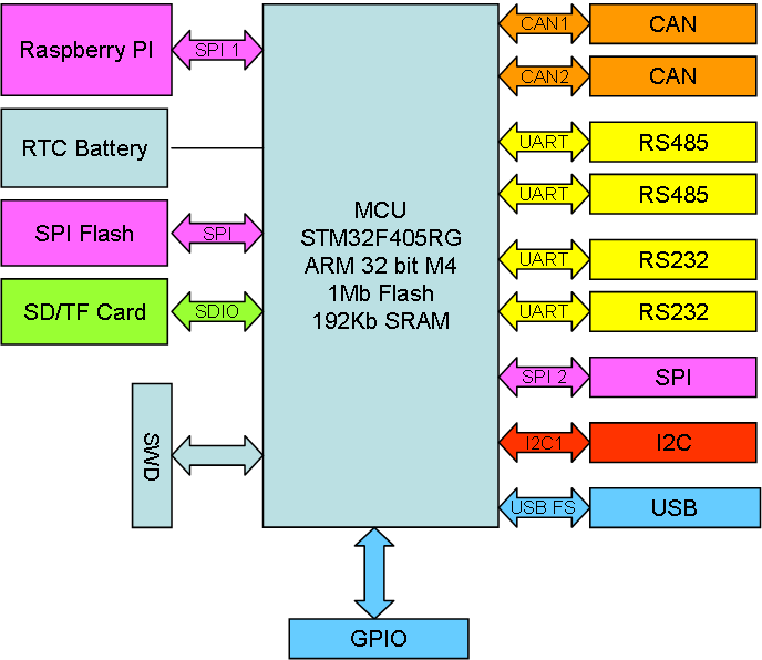
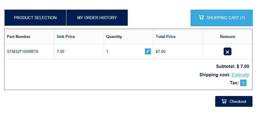
I want to use STM32F405RG, but as you know this can also use STM32F105RB by just replacing 2 capacitors with 0R. F405 and USB means this becomes very available for Python programmers etc.

I am not sure about the SWD connector. I have replaced the 2×5 pin with a 1×6 pin. The 6th pin is 3.3V. I tried using JST Micro connector as SWD and it worked, but I must admit that is much easier to plug in a adapter board on a header. The JST connectors are hard to mount and remove again + wiring on a SWD is a bit critical.

9 port RPI Hub 3D

I like doing these early mock-up’s of PCB’s and adjust schematics because they tell me what I can achieve with pins and space. This is the new RPI Hub I am working on. The details will change, but it looks doable.

  1. 2 x RS485
  2. 2 x RS232
  3. 1 x TTL UART (consume a RS232 port if used)
  4. Terminal switches for RS485/CAN
  5. 2 x CAN
  6. 1 x Serial Flash
  7. 1 x USB
  8. GPIO Expansion Ports
  9. Super-Cap or Battery for RTC
  10. External power connector
  11. 1 x SPI port
  12. 1 x I2C port
  13. Micro-SD Card (MMC).
  14. RPI 2/3 Header

The Hat is in the format of a Raspberry PI Hat. The Hat can be used stand-alone powever by USB (or external), or as a Raspberry PI Hat. As mentioned this is an early mock-up so the actual PCB will change. It will probably take me another week before I order this, so I expect to have

I am also trying rounded corners this time, lets see how that goes. As for usage – this is basically a add-on module for a mobile control system that can operate stand-alone, in a bus or at the back of a Raspberry PI 3A+ or Raspberry PI 3B+ etc.

ST/CubeMX Quality Issues

I really like CubeMX for what it tries to do, but having used it for a while on different MCU’s I also realize that the code it generate is not very mature. On some MCU’s it works well, on others it don’t even compile or as in the example of STM32F105RB temporary brick the MCU. The F105 is also part OpenOCD since CoIDE behaves better.

This creates an issue because I am not sure wherever to continue with CubeMX drivers or roll back to old ones. Luckily I do not depend directly on either as I use my own HAL wrapping in C++, but I need a driver library to fuel this wrapper and it is not really a path forward to use an old library that is going obsolete.

Moving on to IDE discussion SW4STM32 is a possible path forward as IDE, but I am not convinced. I will use it because it integrate nicely with CubeMX making it an easy path for HW testing, but I am far from convinced I will use it for actual Projects.

EmBitz 1.11 looks very promissing being build on Code::Blocks. The only libraries supported out of the box is however the old standard libraries, but EmBitz does also support other MCU’s. I am however not sure exactly how active this project is + I want to go back and investigate using Code::Blocks itself.

9 Port Communication Hub

Updated Article!

I am quite happy with the 5 port Com Hat I made for Raspberry PI, but I want to use a STM32F405RG and maximize usage of all it’s IO capabilities. This will be an upgraded Hat with a few more features included:

  • Replace F105 with the faster and more capable F405 including 1Mb Flash, 192Kb SRAM, ticking at 168Mhz with an ARM 32-bit M4 core. This change will allow Python and .NET to be used as well.
  • Add a RTC w/battery connector.
  • Add a SPI Flash
  • Add a SD/TF Card. I will use a 4 bit MMC version.
  • 2 x CAN ports as before
  • 4 x Serial ports. 2xRS485, 2x RS232 or TTL. My first thought is 2 x RS485, 2 x RS232 and 1 x TTL, but lets see.
  • 1 x SPI port
  • 1 x I2C ports
  • SPI, I2C and available pins as separate extension port. Maybe even throw in a UART TTL here.
  • 1 x USB
  • Limit leds to 1 or 2 pin’s max. We can signal through blink sequences.

I have the pins to do this, so it remains to se if the space of a Raspberry PI Hat will allow for this. I will need to use 3 sides with JST Micro connectors for this one.

PSU here will either be USB or RPI Connector, but I will add a 2 pin 5V power as well.


Bricked STM32F105RB

I am a heavy user of STM32F105RB/RC, but I have not used it much with SW4STM32 before. SW4STM32 (System Workbench for STM32) or ac6wb as it also is called is based on eclipse and uses OpenOCD to connect to the MCU’s Serial debugger. A few days ago while testing CANUSB I noticed problems. First on one MCU, then on a 2nd, 3rd, 4rth and 5th as I just continued bricking MCU’s to rule out that it was the batch.

The library and code here is generated with CubeMX, so I am not sure if it is the generated code, OpenOCD or SW4STM32 that trigger the problem.

I just brought the original MCU back simply by erasing flash with STM32 ST-Link Utility. It worked fine with CoIDE, but as soon as I try SW4STM32 OpenOCD will brick it. Some times it works fine a few times before it suddenly break and I need to bring it back with STM32 ST-Link Utility.

Adding to the story – I downloaded the code generated by CubeMX manually and the same happened. OpenOCD ir SW4STM32 do have a bug because it is not capable of programming the MCU while CoIDE has no problems. But, even STM32 ST-Link Utility cannot connect after code is started, so I need to do a connect under reset – meaning the problem here is the code generated from CubeMX.

This is not the first time CubeMX hits me in the face with a non-mature code example. The tool is great, but I am not able to trust it’s code at precent.

I tried to generate a test project from EmBitz as well, but that uses old libraries for a start and it don’t even compile as it miss the main header file. It just proves to me that I need to manually assemble the HAL myself file for file. I would like to use the newer CubeMX, but I do question their maturity Level.

It also raises a question wherever I should just move on to STM32F405RG. F105 is a real good MCU, but it is less supported than F103 and F405. It cost 50% of a F405, but it is nothing a F105 does that F405 can’t do better. In schematics it is only 2 capacitors that differ the design and they are drop in replacement of each-other on electric levels – obviously F105 have a few less capabilities than F405. I am not ready to give in on F105 just yet, but I am reaching a point where the added cost has to be weighted against time usage and support. And the only argument so far in favor of STM32F105 is that it cost a bit less than F405.

STM32 ST-Link Utility

I have never used the STM32 Server or this link utility before because the IDE’s mostly do the job. But, I have discovered something strange…

After flashing code on a STM32F105RB a few times from SW4STM32 the chip would not download anymore. It happened systematically on 5 different MCU’s, but after using this utility to erase the MCU it worked again.

MCU Cost

This is the cost for a single unit from ST’s own site. Buy 1 million and you get 3.8USD, but you are still not close to the stated cost on their sides. And adding to this you get 20.- USD P&P and Customs and Handling fees.

A single MCU would actually cost me ca 50.- USD if I purchased from here. I think not!

Norway is threatening to start charging MVA on 1st cent for anything imported. It will be a return to the stone age for people like me. It is not the MVA, but the handling fee of 15.- USD they put on everything that will kill electronics import. The did this in Sweden earlier with devostating effect.

Murphy’s Law

Dealing with STM32F105RB I just had the strangest error. ST-Link started failing on my CANUSB adapter and as I tested on a Rx breakout it failed there to. Moving to F405 it works fine and moving to a 3rd board with F105 it works fine.

Two different boards with the same MCU failing at the same time? I guess I just experiencied Murphy’s Law. Another explenation might be that I finally killed MCU’s with static electricity? If so it would be the first time in the last 6 years! It can also be that I am paying the price for picking up cheap MCU’s from various sources. I seriously which ST could provide a way to sell MCU’s in low volumes for prototyping.

ESP32/RPI Adapter – Ground Plane Check

A trick I use is that I connect GND to the ground plane to avoid ground loops. But, what I need to watch out for is isolated icelands that is not connected. I realized that the EDA don’t check this, so I check it manually by using MSPaint to paint the ground plane. In this case it is ok as all areas used actually are connected to ground.


Model Train Control System – Part 4 Connectors

The illustration above show the number of connectors we could need on the Train Control System. I intend to use 1.25mm JST Micro connectors, but space is very limited so this will be a challenge.

  • #1 is the 6 pin programmer port. It is no way to get the programmer with USB connection on the controller so I create a 6 pin program port and a separate programmer board. The intention is to wire this up so we have access to the port below the train. Once this is coded we can also use the Wifi for updates. 
  • #2 is the 2 pin power port
  • #3 is the 2 pin Motor port. 
  • #4 is the 2 pin Super-Cap port. Super cap is like a small battery that will keep the system alive as we move over track gaps. 
  • #5 is the extension port to a 2nd controller board.

To optimize this I plan to reduce this to two connectors. One for Motor, Power and Super-Cap and a 2nd for Programming/Extension. I believe 2 connectors are doable, but I need to draw the packages and make a PCB layout before I actually know.