BSA – Example UML Class Diagram

This example lack a few details, but it illustrate the need for a specialized line where we in this case have a common horizontal level. Without this the diagram would be messy. In this case I have a common horizontal line because all symbols are at the same Y position, but I will need to be able to control that. The solution is that these exact lines need a fixed horizontal level rather than just the mid position as used here and I need to be able to manually control the level of that combined line.

You don’t need to draw class diagrams like this with parts of the line common, but it makes it easier to read. This is just a mockup example so i will return to this detail later as I do UML Class Diagrams properly.

I learned Object Orrientation with OMT which is one of the methods used to create UML and class diagrams are IMO the most important diagram in modelling information because a single, quite simple diagram helps you remember better. The more you remember the better the structure and quality of your system becomes. In BSA I will use classes and class diagrams to model data first and foremost, but you will be able to locate functions drawn in PLD to classes as well.

Precentation is a topic I will return to. Physical classes can contain a lot of details that I am not interested in showing on “this” exact diagram, so I need a precentation layer where I can select parts of a model to draw a non-physical diagram for the purpose of illustrating selected functionality.

The most interesting detail in this example is actually the speed of drawing this example – this is done with BSA and it was drawn in a few seconds. If you try this in most available UML tools you will notice that it actually is a bit of work to get this drawn.

BSA – Next Steps

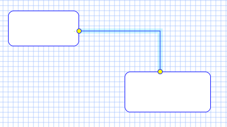
BSA is a huge task so it is important to keep focus to get something that we can start using soon even on beta level. I have done most of links which is the more complex part of the drawing engine. What is remaining is manual link movements. In this first version I will only allow moving end-points. Selecting a link you should get select markers at end-points and be able to drag them anywhere you want. As long as you drag them inside the symbol your link will stay connected, if you drag it outside the symbol your link get deleted, if you drag it to a different symbol your link get re-connected to that symbol etc.

For now I will avoid letting the user fiddle with the rest of the line. I will add that later. The Line Calculator is quite good and a reproduction of work I did 26 years ago. As I mentioned earlier – automation is key here – avoid that the user have to fiddle with lines.

Once lines are done I need to attend to the property editor, saving/loading diagrams and finishing first level of GUI components before I finally can start generating code towards my first target platforms.

This first version will be able to select pre-defined signals and connect them to objects on the screen, but it will not be able to do much processing on the signals before I get the other diagrams up running later. I initially hoped to have a prototype available around now, but the issue is that I am not allowed to work as much on this as I want to + tbh some of the logic and work is rather complex to get the way I want them. That said, links are the most complex part to get right.

Stay tuned, this will be an interesting summer/authumn!


BSA – Merging HMI into PLD

This is PLD where I use HMI Form as building blocks. I am not sure about this idea, but a HMI screen is a complex object with multiple paths and PLD can actually visualize this. in this example I show what other HMI forms are called, but it could as well have been the menu actions in the form. I see a challenge in that a HMI screen will have far to many events to be displayed in a single diagram like this – but, lets work on that and see what we can get out of this.

As I work with complex GUI applications I often lack this exact overview and spend time looking for functions that process on xxx event – maybe a button event, a meny event or a process event. Maybe I can use PLD to visualize this part of HMI design?

The next diagram below is just another way of displaing this. It is basically a call graph that also can be replaced by a table showing events and what happens with them. It does not need to be graphical. An auto-generated table might be more usefully with regards to the amount of events in this case, but it is basically nothing preventing the user from doing this in PLD either. I need to let this idea ature a bit.


BSA – Automated Lines

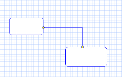
This test diagram shows some of the automated lines used in BSA. As you draw diagrams you also need to use line (or links) between the symbols to create a diagram. But it is important to remember that we are NOT making drawings, we are creating a specification where the lines are translated to source code later – and the worst thing you can do is to create a tool where the user end up fiddling with lines to get the diagrams to look pretty. If you do that you slow down the programming speed of the developer, so lines must MUST be automated. They should look ok from start and the user should not need to do anything but fix their end-points.

I worked on CASE tools in the past that was horrible as you spent hours fixing diagrams to look nice. The next version was better with regards to lines as they automated more. I have accidentally been working on some of the worst nightmares of CASE tools. Their concepts and ideaes was good, but they created dinosouruses. That is what we used to call the old CASE tools – dinosouruses. They did a few things good and the rest was non-functional and at the end they did not deliver on productivity. CASE tools as an idea have been around since early 80ts, but to day no-one have managed to break the barrier of making a CASE tool go into the main stream of development due to (1) price, (2) lack of automation or lack of feature support, and (3) lack of integration with 3rd generation programming languages. It will always be (1) a need for assembly, (2) a need for C/C++ or similar – old fashined, low level languages that are hard to replace if they are needed. A modern tool should build on that and extend, not replace lower layer tools. This is a core concept in BSA.

I keep repeating this because BSA is not easy to create and it is very easy to go wrong on features that end up slowing down the user rather than increasing productivity. And for a tool of this category to be successfully it must be available (as in low cost) and have a none-questioned productivity gain on development alone with no show stoppers. Many users give a sod about documentation, software-architecture, increased quality, 100% automated testing and such. These are often low priority compared with the capability to deliver and maintain a working product. And even thos companies that require increased quality often can’t afford the tools that could help them out. A price tag of 10k – 100k per developer is usually a blocker for availability.

Back to lines – BSA will automate the lines – the user should never need to manipulate line drawing. But, that’s the theory and then we need to deal with the dinosourus effect – the exceptions – it would be stupid not to give the user the option to manipulate lines manually as well. The way this is planned is that the user can select between several line automation techniques or simply take over and draw a manual polyline if automation do not deliver the required line.

Getting lines correct to make it easy to sit back with nice looking diagrams is an important win. The next step is to move diagrams into documents like Software Architecture and automate as much of the doc task as possible. While many probably will use BSA itself as doc, it is still those amoung us that like to see a nice web page or an old, fashoned document in Word, PDF or openOffice/liebreOffice etc.

BSA is capable of letting the user draw hes own diagrams with hes own symbols. That is what you see above. The diagram engine still have some work in progress, but it is coming on. I used the last days to port an old Line Calculator over with great success, but I need to focus on my first release which is HMI design.

Thanks for reading and stay tuned…


BSA – UML State Diagram

I got the first link designs connecting symbols working. I will not use much time on State Diagrams in first round as my objective is still to create GUI designer first. But, working on advanced, embedded solutions every day I am actually looking forward to be working with BSA once it becomes fully functional. The difference is that in a normal developement you need to attend to all the nitty, gritty code details on multiple devices yourself – while in BSA you specify a specification that is auto-generated into code. In other words you change mind-set from HOW to do things into WHAT you do.

The primary work now is getting the graphic engine working. I am very happy that I switched from QML to WPF. That said – I actually liked QML, just not the hours it took to make something. But, I work in QML as well so getting a GUI designer that support Qt/QML , WPF and Embedded are my first targets. To be realistic we will see the end of July before the first functional version is in Beta . it is a bit left to do + I struggle to find time working on this these days – that is real life for you.

It is going to be a few try and fail on concepts as we go forward. Making a graphical programming tool like BSA is not straight forward. The reasons no-one have properly succeeded yet is because (1) few users give expensive tools that is not available for most, (2) graphical drawings are slower to work with than you expect.

Looking at the diagram above you actually see one of the challenges – details needed for executable accuracy is hidden. The is partly deliberate to force you into a WHAT mode, but it is in your way then you want to check logic. The option is that you need to click on each symbol to check details – which is a clumbsy way of reading source code – so I need to work a bit on this one – how to increase visibility of nitty, gritty details then you need them.

All this has to do with one single objective – speed of development. Having diagrams is somthing I do regardless to have better overview of larger projects. used correctly they do a lot to the quality of your projects. Having them a way of coding should significantly increase your coding speed – but, you need to be aware that specifying logic on a graphical editor is much slower than on a simple text editor if you do it 1:1 – this is why BSA must be an extension to ordinary programming platforms like C#/WPF and Qt/QML – not a replacement. I still intend to write building blocks for BSA in C++, C# or whatever. BSA should deal with WHAT you do and leave it to clever programmers to make the HOW logic in whatever they need.

As mentioned a few times – BSA focus on distributed systems. In this example we could easily be sending a signal flow between computers coding one block on STM32 and another on a PC in the same diagram. This abstraction is something that is easy to do with a UML state diagram as show above.

I have tweaked the standard UML State Diagram symbols a little. Mostly the terminals that I decided to merge UML State Diagrams with what I planned for PLD. But, it is still a UML State Diagram. You have to expect a few tyweks like that as some parts of the model standards need to be adapted to executable accuracy.

The terminals are input/output signals with parameters. The diagram itself become a building block you can use in the next diagram etc.

BSA – Coming alone

BSA is coming alone, but it is still a lot of work before this is functional. I lack symbols, details in symbols, line editors etc. But, the graphical work is going smooth and the rest is just “ordinary”C# coding. I am a much bigger fan of C++ that C#, so it is ironic to chose WPF over QML. But, I am a big fan of getting things done and C# is the right choise for a heavy Windows application.

I will reconsider dark theme as soon as I have an overview of the controls I will need to re-design from scratch. I have decided to not bother to much with changing existing native controls as it in many cases are much easier to just write your own from scratch. This is the same I did in QML and was doing earlier in Qt and C#/Forms working on this. Shape is awasome that way because every single graphical element is a complete UI. Invisible for the eye it actually is 5 graphical layers on the diagram – or well drawing as this is no diagrams yet.

I intended to be done with the Forms designer ca June before I switched from QML to WPF. I think we will see July before I can finish a Beta, but that is pretty awesome taken into account that I only work on this spare time and started ca 1 month ago.

It annoy me a bit that I can’t do the cooler dark theme, but if I start on that I will need a lot of time converting Windows native controls. I had the same issue in QML as I basically had to spend a lot of time on things not related to BSA. Stay in touch.

BSA – WPF Selectors

One of the challenges with GPU drawings is the selectors used to resize an object. In this case I have drawn 3 rectangles and have the selectors as part of the rectangle drawing using a different ZIndex.  Sadly the ZIndex only work on the locat drawing, so as the middle is selected it’s selectors are hidden behind the object in front of it. The 2nd challenge is that selectors are zoomed as the diagram is zoomed, meaning they can get very small.

One possibility is to have a 3rd diagram for selectors. The grid is on a separate diagram that is in background. I can do the same for diagram UI which in that case would include more advanced UI controls for rotation, in-line edit etc. That will work since the ZIndex on the new diagram is in front of the two others – just keep the background Transparent.

BSA – DataSource

This is an updated drawing of the DataSource concept in BSA. The idea is that easyIPC provide an uniform access method so that the HMI user don’t need to concern himself with how data arrives or are sent. easyIPC have it’s own native transport protocol and network, but must be able to interface to other known protocols and technologies.

Modbus is easy to implement and to well used to be ignored.

CAN/CANopen is a candidate. CAN have multiple protocol candidates, but I have only used CANopen myself. The protocols used in vehicles are often proprietary variants and CANopen is not a good protocol in the first place. It is old and I was told that the first draft was signed in a hurry because someone had a plane to catch.

Database is a subject by itself, but we need to find methods to integrate the most popular ones at least. We also need embedded database operating on small SPI Flash etc.

Memory is RAM/SRAM on your node. BSA itself uses a heavy RAM based database as an example. But, the idea is that the user can design RAM based tables and use them as if they where a Database.

File system can be a hard disk, Flash or SD/TF Card etc.

The main concept here is that a UI control is binded with a variable and the rest is “magic”. In the first version of BSA I will focus on HMI design so the DataSource will need to be coded maually outside BSA, but as we move on we will be able to add logic to DataSource events as well.

One important aspect is that a user who insist on using Modbus registers directly must be allowed to do so. He/She should not see the difference. This is straight forward as long as the source is one the local computer, but a bit more complex as we introduce a network. But, this is easyIPC’s problem as it need to support “Modbus over easyIPC”. The same goes for CANopen and other protocols even lower layers of easyIPC.

BSA – GPU vs Raster graphics

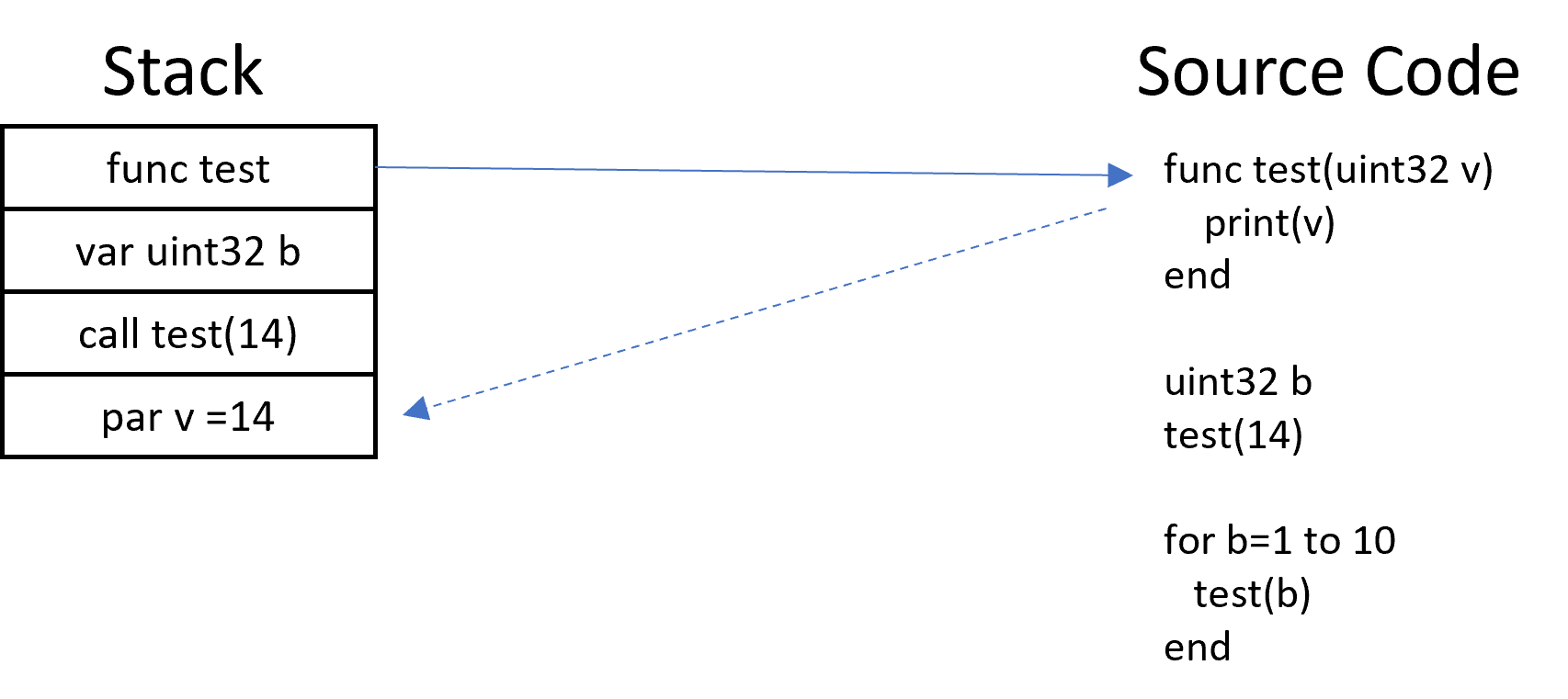
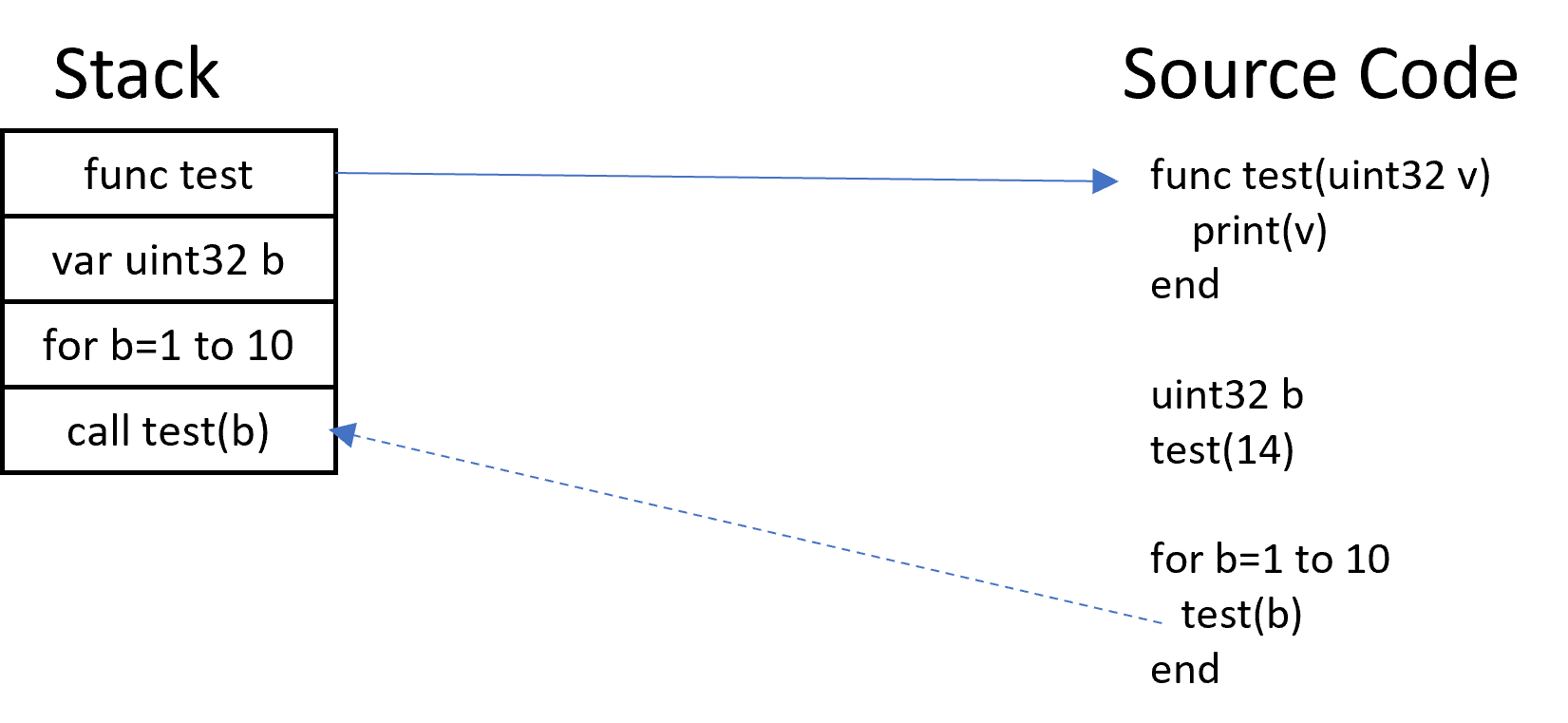
The drawing above show the classic Raster Graphics where the drawing is done directly on the screen by a CPU. This is how classic Qt and C#/Forms works.

The drawing below show the same with WPF/QML involved. The code (or QML/XAML) will in this case create and object that we can manipulate from code, but drawing is done by the GPU. This causes some changes moving from raster to GPU graphics as you only can manipulate the object through commands.


BSA – WPF Line Moving

The diagram above show an actual PolyLine on a diagram – or more correctly two lines. Drawing shapes you get automatic hit test support as the mouse moves over the line, so only a few commands was needed to implement a Line Move feature. The chellenge was more that a line with thickness 1 was hard to hit, so I cheat and put an invisible line with thickness=10 above. This works perfect and it was straight up moving on scrolling and zooming. I still need to add joint markers so the user can do more than move, but this one amazed me of how easy it was. I do pay the prize of drawing secret lines, but the advantage is that I can set color and transparancy=50 (as above) then mouse hit – it is actually very cool.