One of the challenges I face using wireless communication is that it requires a bit of power/time to send signals.
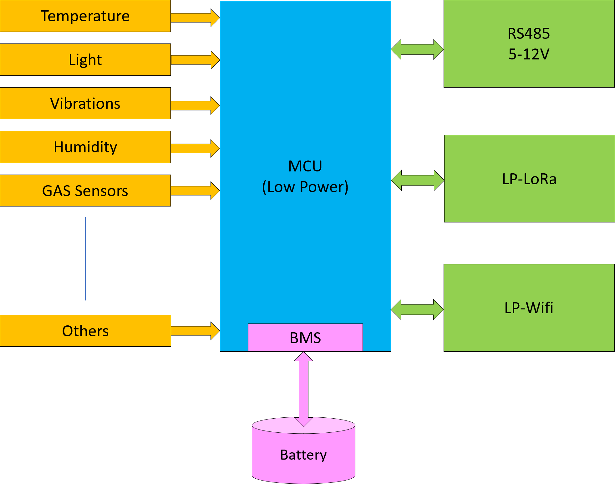
Wifi : ESP-M1 is the first solution I evaluate. This is the smallest of the ESP modules and can send using 120-170mA. Simply speaking if you have a battery with 1000mAH or( 1AH) you can operate non-stop in 5-7 hours. So the classic technique is to switch off and only send then you need to. But, even in Rx mode we use typically 20mA and using that as base we have 50 or so hours of operation. We are still far off where we need to be. Deep sleep mode for this ESP module is <10uA according to the datasheet. 1000 / 0.01 = 100,000 hours meaning we suddenly talk about 10+ years in that mode assuming we use a 1AH battery. But, I can’t do much in deep sleep mode and I am surprised over how long time I use to connect and send. Testing on my table suggest up to 10 seconds since the ESP-M1 needs to connect to Wifi first.
Assuming I send once per minute (using 10 seconds to send) that gives me a ruff calculation 1000 / 200 * 6 = ca 30 hours of operation. Every 5 minute is 150 hours of operation etc – every hour ca 1800 hours operation etc. These calculations are a bit ruff, but they show that with 10 seconds connect & send time we will be struggling unless we upgrade once per 24 hour in which case we would be up in ca 43200 hours. The key here is to see if we can reduce that connect and send time. I think that reporting once per minute is a minimum for sensors.
ESP-M1 have a deep sleep mode that uses 20mA that remain connected to Wifi, but that alone will reduce us to 1000/20 = ca 50 hours of operation. The reality is that we need an average current consumtion on ca 100uA or lower for a 1AH battery to last a year on that battery.
Testing ESP32 connection time I get connected within 5 seconds, while using ESP-M1 I need closer to 10 seconds, so a classic ESP32 might be more optional that ESP-M1 for low power. But, we are far away from any solution that gives us 1 year+ on a 1000mAH battery. I need to dig further into this as using Wifi + battery is my first choise.
