I have been very slow on ordering PCB modules for my latest PLC, the reason is because I have so many designs laying around lacking firmware as they only reached the proof of concept level. But, I am finally pushing these modules. It is five modules that will be created now because I need those for my larger, mobile CNC + I need them as experimental targets for BSA.
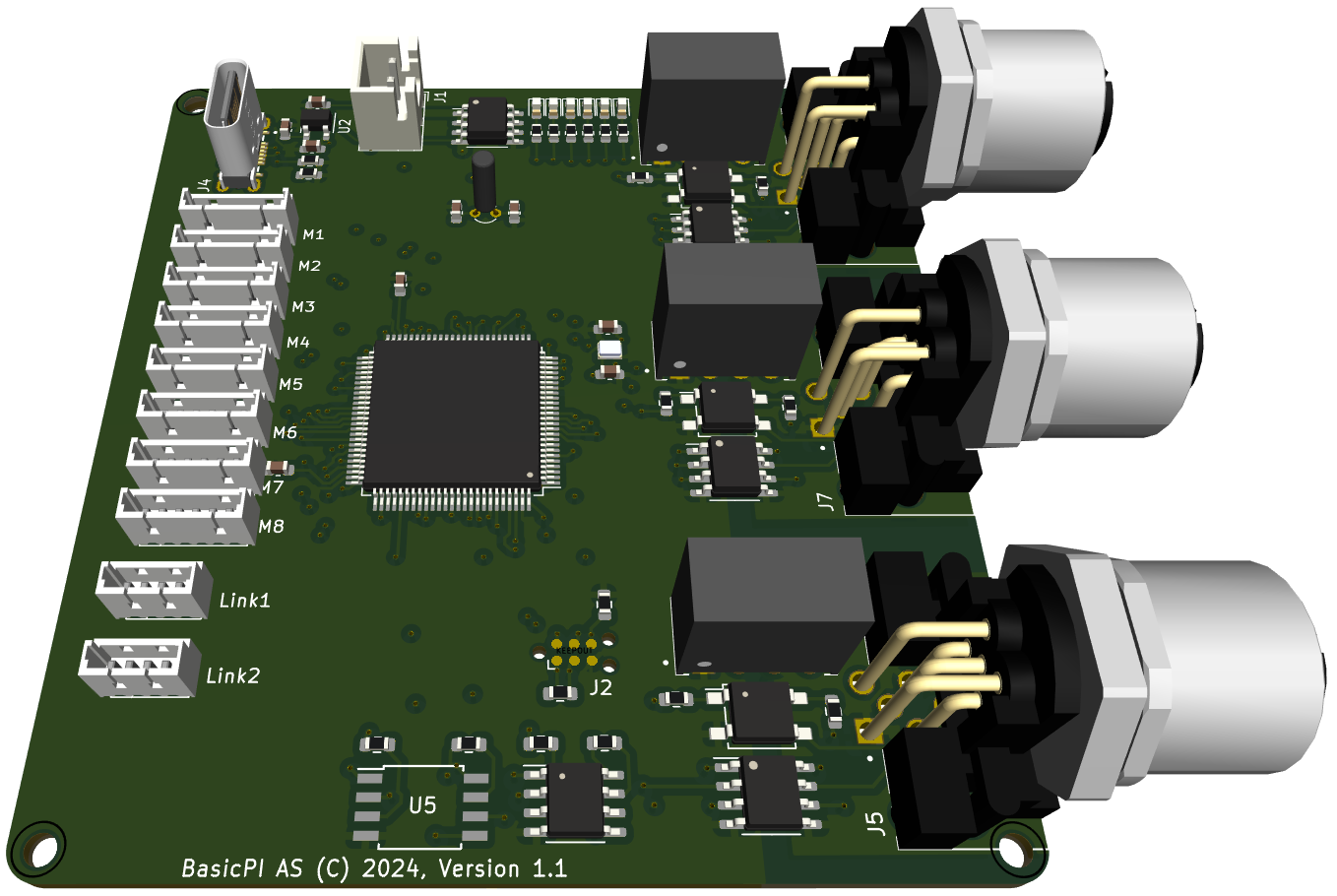
This first module is the core MCU module with 3 CAN ports and 10 Expansion ports as well as USB port (Development only) and Flash/FRAM.

The second module is the Servo Driver capable of driving a 5A Servo at 8 or 12V etc. This is designed specially for some of the power servoes I have that require a special voltage and some juice to operate. To be honest I am not sure if 5A is sufficient, but we will find out.

The third module is a new 4 x Half H-Bridge module that is very flexible as it can drive 4 separate solenoids, 2 DC motors or a larger Servo. This is designed for the wheels I have as I am still evaluating wherever to use a DC Motor w/Encoder or stepper motor. This module will support them both.

This is an unshielded 24V to 5V PSU dimensioned for 5A on 5V and 5-10A or 24V.

This last module module is an Ethernet-Module. This will be a candidate for upgrade later as I currently use W5500 from Wiznet. In future I will look for a MCU with Ethernet on chip to perform this function.
Version 1 of the device nodes uses a STM32G491CE that is a powerfully, but expensive MCU. I stick to this because I have a storage of them and have trouble getting hold of STM32H503CB that I want to use on the version 2.0 of all devices. H504 have less Flash/SRAM, but is far cheaper and running at 250Mhz on a M33 core they are pretty powerfully. I will change to H503 before I put the moduls in production as it saves around 5.- USD per modul.
It is also a design error on these first modules as the 5V and 24V connectors are identical. This must be changed on version 2’s as it should not be possible to interconnect 5V and 24V as it currently is. But, I am confident I will find other issues once I get the PCB’s in January – I usually do – for now I leave it as is.


