BSA – Abstraction Layer

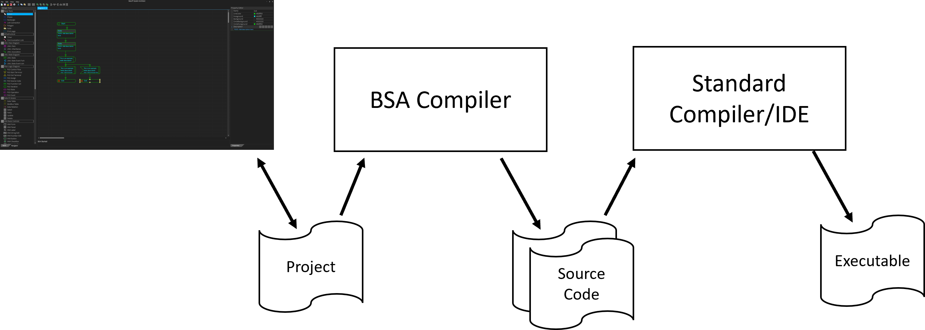
This block diagram only illustrate a few of the modules in the Abstraction Layer – loads of more will be added as needed. I started this library years ago so it has existed in various versions, but are re-designing it to be cleaner now. This is a C++ library designed to make coding of user applications fast and easy and will contain a variety of modules that is needed organized in a matter that makes sence.

At the bottom you have native HAL drivers. ESP32, ESP8285, Pico and STM32 have different HAL libraries, and while it is funto write bare-bone libraries using registers etc it is also to time-consuming, so I leave that to people with more time & interest. I will write bare-bone and even assembly as needed, but only if needed.

Ethernet & Wifi are full TCP/IP stacks with extras.

LoRa is Long Range Radio covering up to 10km of range with reduced bandwidth.

Display is a generic display interface consisting of multiple LCD/TFT drivers.

FRAM and Flash are various persistent storage technologies.

GPIO, RTC, ADC etc are interface to various IO technologies.

System is a the rest including RTOS and timers, stuff that I want available on all platforms.

The cost of doing this is that I bloat the Flash a bit – currently working on STM32F401CC (Blackpill) I use ca 60Kb Flash (30 with optimization), so it’s not that bad. But, using this library on less than 128Kb Flash will be tight because it will have a lot of content. This is a trade – functionality – time to marked – versus flash.

I use this manually for now as I create the library, but BSA will generate code towards this.

BSA – Abstraction Layer – Documentation

If you have ever written a driver or picked up someone elses code you will recognize the need for documentation and examples on how to use it. I am writing loads of drivers these days and stugle with Vendor datasheets as well as HAL’s – usually I end up hacking and trying to understanding how it works and finally implement my own driver in a C++ class. If I left it there it would only be yet another layer to understand – for code to be really reusable you need documentation and examples.

Reading datasheets should normally solve the need for doc, but I often find that information is left out or that it actually work differently than expected – these details are crucial to get down in code and doc. Maybe it’s me who have misunderstood something, but if I don’t write that down you will struggle to correct my mistakes or improve my code.  I am no different than other developers – I like to do my own things – things that are productive for me. I have mates that do the same, but their things are seldom productive for me unless they bother to complete and document their work.

One of the worst tasks you take on as a developer is to try to fix someone elses work that is half-done, not tested and with no doc. That is what I am doing at moment – it’s no fun 🙁

Abstraction Layer – alSystem

I typically code ESP32, ESP8285, a lot of STM32, Pico, Linux and Windows to mention a few, so I want to be able to move code between those platforms with a minimum of hazle. For this purpose I create a C++ API that I call “Abstraction Layer”. I did not want to use the word “HAL” because it is not always hardware that I abstract away from. Another motivation for this layer is C++. Nearly all code, drivers etc for embedded is in C, while I have a very strong preference for Embedded C++.

The first class (module) I need is “alSystem” that allow me to access platform specific content in a generic way – simple things like sending signals, starting/stopping threads, tasks and timers and measuring time. Both FreeRTOS, Windows and Linux offer these mechanisms, but how do I move code between a non-RTOS, RTOS and Linux/Windows? The answer is that I hide them behind a class called alSystem.

Example:

uint32_t now = alSystem::millis();

This is a simple function to fetch the time in ms since the computer started. It is often used to measure time difference in ms, so I create a 32 bit version and a 64 bit version of this. I also create micosecond versions, but the later are seldom of any usage because we usually don’t maintain time below milliseconds unless we have special needs due to the complexity/cost/performance. The challenge with a 32 bit ms timer is that it wraps in ca 50 days, so if you want to make it secure you use a 64 bit version since uint64_t is supported.

  • millis()
  • millis64()
  • micros()
  • micros64()
  • delay()
  • sleep()
  • CreateTimer()
  • StartTimer()
  • StopTimer()
  • CreateTask()
  • SignalTask()
  • CreateThread()

These are a few of the static functions I always replicate in alSystem that will be guaranteed on any platform I use. Not everything is created inside alSystem as I also have a C++ library with power classes tailored specially for a static, embedded system where new/delete is forbidden – no memory allocation once the system is started.

This C++ layer do come at a cost of more Flash usage, but most MCU’s these days come with a bit of Flash and what I need the least is Flash I don’t use. This means I cannot use this library for very small cost-effective MCU’s, but for those I would code bare-bone C anyway. This library target more intelligent platforms where functionality and AI is in focus.

And least, but not last – generating code from BSA will use this library as a base – that simple trick allows me to generate code for multiple embedded platforms.

HMI – Display Abstraction Layer

I am working on “alDisplay” that is my embedded abstraction class to LCD/TFT diplays. This is quite a challenging task because I will have to deal with how specialized and proprietary these displays are and on top of that performance. The drawing above illustrate four layers – in my case actual hardware (orange) and three classes – I use alSPI, ST7735S and alDisplay. The user code will only see alDisplay and a very normalized interface, so if I swap display hardware that will be invisible to my code.

alDisplay will typically have functions like clear screen, println etc.

ST7735S will have a normalized interface for the alDisplay class and a specialized, proprietary interface for SPI.

alSPI have a normalized SPI interface.

This will bloat a bit, but as I will be using various displays it is a must.

Performance is a bitch as it might force me to use proprietary operations all the way from alDisplay with “#ifdef” code, but usually performance on a display is achieved through some memory moves that I hope to make common.

As for the reason I started this ? Available drivers will force my code to handle display differences, but more important I tested a display and a driver that don’t work. I might have a broken display, but decided that this layer have to done if I want to avoid spending endless time on different displays. I am also a bit fuzzed by depanding simple, straight forward, easy to read code!

SPI Error

This is an error! in my wisdom I decided to always select a SPI Flash not realizing that CS signal mark the beginning and end of each command. nCS needs to be connected to a GPIO pin for SPI based memory to work.

Home Automation – Battery lifetime

Ferrite RAM is one of the older RAM techniques used on old mainframes dating back to the 60s, but have in recent years also been popular as a replacement for EEPROM and flash because it is fast and have close to unlimited rewrites. I recently purchased a bunch of FRAM chips with the same interface as SPI flash in SOP8 format. This is excellent for the Blackpill that is a STM32F401CC  breakout board with space for a SPI Flash on the back since they use the same footprint. These FRAM chips cost around 4.- USD and will only have 32Kb (kilo byte), but that is excellent for my usage.

STM32F401 is not ideal for a low power battery operated application, but with the current MCU shortage I decided to give it a try since it is available with a breakout costing around 3.- USD in dip40 format.

Despite being hight performance and not low power the STM32F401CC is still capable of dropping down to uA while using only RTC and executing sampling using < 10mA. Reading an ADC (temperature) can be done once a second at very low power on a 1000mAH, 3.7V battery. And with a FRAM we can wake it up, read and write to it and be done within 5ms giving the battery a decent lifetime.

My first application is a simple temperature sensor that uses radio. I will sample to a FRAM and then connect to a server and transfer the FRAM content. To do this I create a simple array on FRAM storing time and temperature every second and every 10 minute or so I wake up a LoRa and send the content starting over.

I considered using Wifi (ESP), but realized that connection time on any Wifi unit would be 3-7 seconds with 150ich mA – far to high for battery usage. So I will test LoRa. The first usage will be 1-2 units only for testing.

I have also purchased STM32L4P5CE MCU’s that is much better on low power than STM32F401CC, but these are also more expensive and difficult to get by these days. And it is not the current usage of the MCU that is my main concern – it is everything around the MCU – Temperature sensor, FRAM, LoRa sender etc.

I plan to add far more sensors than temperature, but I need to experiment with low power solutions and temperature is a simple, good start.

In the Blackpill case I will need to put FRAM in sleep (12uA) and wake it up which takes ca 0,5 ms – while operating it uses 2.3 mA and I think I can finish this part within 1-2 mS which will be great for my battery budget.

Home Automation – Wifi battery operation time

One of the challenges I face using wireless communication is that it requires a bit of power/time to send signals.

Wifi : ESP-M1 is the first solution I evaluate. This is the smallest of the ESP modules and can send using 120-170mA. Simply speaking if you have a battery with 1000mAH or( 1AH) you can operate non-stop in 5-7 hours. So the classic technique is to switch off and only send then you need to. But, even in Rx mode we use typically 20mA and using that as base we have 50 or so hours of operation. We are still far off where we need to be. Deep sleep mode for this ESP module is <10uA according to the datasheet. 1000 / 0.01 = 100,000 hours meaning we suddenly talk about 10+ years in that mode assuming we use a 1AH battery. But, I can’t do much in deep sleep mode and I am surprised over how long time I use to connect and send. Testing on my table suggest up to 10 seconds since the ESP-M1 needs to connect to Wifi first.

Assuming I send once per minute (using 10 seconds to send) that gives me a ruff calculation 1000 / 200 * 6 = ca 30 hours of operation. Every 5 minute is 150 hours of operation etc – every hour ca 1800 hours operation etc. These calculations are a bit ruff, but they show that with 10 seconds connect & send time we will be struggling unless we upgrade once per 24 hour in which case we would be up in ca 43200 hours. The key here is to see if we can reduce that connect and send time. I think that reporting once per minute is a minimum for sensors.

ESP-M1 have a deep sleep mode that uses 20mA that remain connected to Wifi, but that alone will reduce us to 1000/20 = ca 50 hours of operation. The reality is that we need an average current consumtion on ca 100uA or lower for a 1AH battery to last a year on that battery.

Testing ESP32 connection time I get connected within 5 seconds, while using ESP-M1 I need closer to 10 seconds, so a classic ESP32 might be more optional that ESP-M1 for low power. But, we are far away from any solution that gives us 1 year+ on a 1000mAH battery. I need to dig further into this as using Wifi + battery is my first choise.

Home Automation – Closed network

A lot of IoT/Cloud solutions focus on access through internet, while I want a closed network of sensors in my house with a switch that enable very secure and restricted access from outside that network. I don’t want it to be fysical possible to break in without fysical access. But, I want to use Wifi and Wired solutions to connect sensor units in my home. Using a combined multi-sensor as described before means I can get away with one unit in each room.

The advantage of this is that I can use the information to provide simple automation logic at low cost. The most obvious start is temperature in each room and the capability to save electricity by lowering temperature in unused rooms and at times of day based on simple logic.

If I go on holliday I can enable my own phone or tablet to access this through a secure connection where only my physical device can be used. The thing is that with internet you never know as some smart hacker might always find a way in, so the best security is to disconnect internet completely. Wifi is a bit more secure as you need to be in ca 100 meter range and we can have the units to auto-change security passwords etc. Even better, we can also use wired, secure connections if we want to. Just keep in mind that a wired connection also is wireless on ca 50cm distance with correct equipment.

As for functionality I can add camera and voice units as needed, but me in person I believe things like Alexia or similar is useless crap at this point.

I have my PLS stack that I will use for actuators, but I need to create the sensor unit and I want to start with a low, cost battery modul with Wifi. 3,7V battery have the advantage that I can go direct without a regulator and use something like ESP32 as core for a simple, cheap start.


Home Automation – Sensors

I have always dreamed about automating my own home and one of the key starting components are low cost sensors. This technology is available today, so it is not rocket science, but I want to create a low cost practical system. Starting with sensors only I would like to monitor temperature in every room in the house as a start. If I can monitor temeperatures I can control heating – it is a simple application that any modern electric owen can do, but I fancy doing it through a centralized system and to deal with some of the challenges I face getting there.

The concept drawing abobe illustrate 3 different communication options as well as some sensors and a battery solution.

Battery is a challenge because you will either need to recharge batteries or swap batteries on regular intervals. But, battery combined with Low Power Wifi/Lora is the most elegant solution. The option to use a cheap network like RS485 (or similar) and power cables. You then get 4 cables to each sensor. The drawback with the RS485 solution is that you need to drag cables around the house. I think it’s ok to have a system that can do both specially since the RS485 option hardly require PCB footprint at all.

The pink part – BMS and batery is quite simply a voltage sensor on a 3,7V LiPo or similar. We don’t charge, but we can monitor battery state and give a low power alarm.

This block diagram is rather generic, but I think I can manage it all in one circuit which will be better for higher volumes. I have a L4 Nucleo board I can use as a start. Standard for all the sensors are that it is of little extra usage to monitor them constantly, so we need to work out a time scheme. Starting with temperature I would say that measuring the temperature every 10th second is more than sufficient. That means we can sleep in 9.9 seconds and just switch on a minimum of power for a little while. Being intelligent we can also decide if temperature have changes sufficiently for use to switch on the radio and report anything. If we do this with every sensor we should end up with a pretty good low power scheme where a seleceted battery cam last a predictable period.

As for form factor I am thinking a bigger board this time. Most of the cost here can be lowered more with volum than with size, so having a larger PCB that can do more makes sence. I can then configure that as I please for each room. Lets at least start with this.

New Motor Controller

I recently bought a test kit (ESC) from ST that I used 2 days on to create a motor controller, and I liked the design so I am using it as template for a new controller. You will remember that I created a “ThunderStick” using DRV8301, basically a controller very close to the Vedder design. But, I have created controllers closer to the ST design before using 4 discrete gate drivers, so I want to go back to this design and see if I can upgrade my ThunderStick to ThunderStick2 with a few changes. This is the real reason I bought STM32G491. The ST kit uses STM32G431 that is close to identical with less Flash.

I want a few changes from ST design:

  • I need 60-100V MOSFET’s because I need 48V on the drones. 24V is to low as it makes it more difficult to drive the larger drones.
  • I want a larger controller with proper connectors – more like my 100mm x 25mm Thunderstick.
  • I want a similar heatsink as on Thunderstick.
  • I add a FRAM (or SPI Flash) for storing variables.
  • I add a serial interface, but uses CAN for control.

This is a quick draft so it might be changes, but I have done a few motor controllers now so I think I can manage one that has a good compromize on size/heating. The ST kit is cool, but close to useless because it is so small. Thunderstick size is larger and have a much better design to get rid of heat, meaning I should be able to achieve higher currents – more effect out. Thunderstick is also a very good form factor for larger drones that I focus on.

One of the things that is special with the G series is their analogue content. G431/G491 have 4 Programmable Op-Amps and Comparators as well as 12-16 bit ADC channels that is perfect for a small size motor controller. I am actually looking forward to redrawing this with KiCad because Thunderstick was hard to make a PCB with using Target.

Moving on – I have been working on my own PLC system for drones/homes for a while and will update many of the boards I have made and actually get them into production. Many of the boards have been experimental and been working well – which is not bad for a hobbyist.