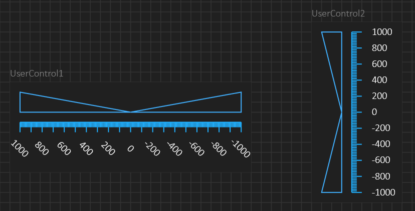
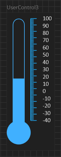
BSA – Circular Gauge – Part 3 – Integer Error

A common mistake then reprecenting pixel positions is to use Integers. This is how we did things back in the 80’s and 90’s, but GPU’s use double and pixel 1.5 actually exist. As the GPU smooth lines it will add shades to make it look as if we have pixels between pixels. If your coordinate system is integers only it will mean that a figure that is moved on screen jump one pixel and look as if it changes a little. So in dealing with graphics – always use double and never round off because the GPU will make use of the decimals.

BSA – Circular Gauge – Part 2 – The Pie

The reason I don’t want to copy pre-made gauges is because I want to create the gauge layer by layer and then have the option to stack whatever Gauge I want. WPF provide a few graphic shapes like Ellipse, Line and Rectangle, but the rest you need to add yourself. This one is a Pie. Drawing an Arc in WPF is suprisingly difficult as the functionality is hidden in classes you need to use to draw a path, but the resulting Pie used here is straight forward to use. Drawing is however very easy (and little code) once you use the correct function in WPF.

This alone allows me to create simple gauges, not to mention that it actually also can be used as a Simple, 2D Pie Chart.

One important issue now is range setting. Since this is designed to be part of a complex component with multiple layers we probably would preffer to have common range setting to avoid to duplicate them everywhere.

BSA – Circular Gauges – Part 1

Working on BSA I have been through a lot of work to style common controls in WPF and QML to make SDK’s I can use as I generate code. Most of this work was doing the designer part in BSA, but in some cases I also had to create the controls themselves from scratch. Starting on gauges it become more obvious why we have to hand-tailor these controls. Commercial libraries exist, but for WPF it also exist a nice collection of librarary components out with CPOL or MIT licensing. so it’s no reason to pay 1000.- USD for a subscription fee on a library. That said I can’r do the same on QML. But, I have written numerous gauges before and both QML and WPF is easy to work with in this aspect.

This is one example that I found of CodeProject (A WPF Rotary Control – CodeProject) – excellent example for getting ideas and alearning how other have solved issues. I could actually have used some of these, but I am more interesting creating my own gauges from scratch nicking ideas from others. The issue with WPF (and QML) is that you need to be a little bit carefully about how you design things. As I learned with the property editor the GPU will do the work, but loading it to a GPU might surprice you. Another issue is that I am not interested in creating final gauges . I will do that as well – but I am more interested in disecting them and create their components one by one in simple forms so they easily be assembled as a more advanced gauge.

If you look into code you will see that this is more or less how everyone build their gauges layer by layer, so it is not rocket science.

So many parts of BSA have now come together that it’s time to start working on the SDK’s needed to generate code – which will be a bit more visual and fun to blog about. And this work will be done in both WPF and Qt/QML.

  • Advanced Real-Time plot
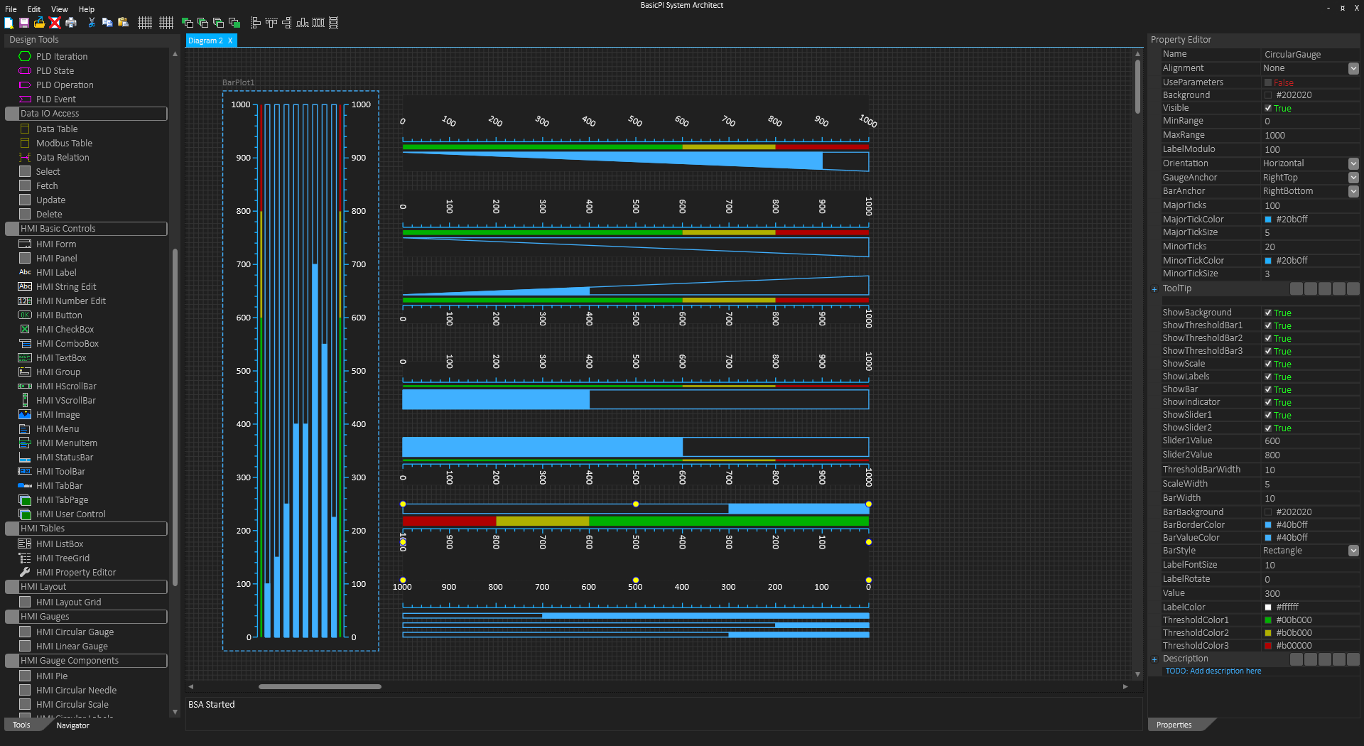
  • Circular Gauges
  • Linear Gauges
  • Fast, Real-Time Table

Those are the four on top of my list.

BSA – Tables

This ModbusTable is only 100 entries and behaving very nice due to a trick where I only load row details if the row is expanded.That trick will allow  me  to  create  tables up to ca 300 entries and still have decent behavior, but it is no solution for very large tables. So I  will  need  to  find/create  a proper  solution.

The old trick is that you only load the portion you see and re-load as you scroll. This is how virtual tables work. In that case you can have a table with millions of rows and still have a very fast screen without the hazard of running out of resources. As mentioned a few times I seldom think to much about performance these days, but in this case I must because with large arrays loaded into PropertyTree loading becomes a bottleneck. The UI feels slow and little responcive even with 0,5 sec delay on a click.

Moving on a little I also need to solve this as user components. WPF have a good grid “DataGrid”, but I want a TreeGrid and a high performance RT Grid as well. The later is a simpler grid focusing on displaying text only rows at very high speed. And I also want the propertyeditor as a component at some point.

BSA – Modbus vs other protocols

I am very pleased with how I integrated Modbus as far as the result goes, but it has been a bit of hand-tailoring inside BSA – I am not so happy with the later because that is not a generic solution. So I need to find a way to create user controls the same way. The question is if I need to add a protocol designer? I need to think about that one.

BSA – Bad got Worse

This shows BSA with a 64 register ModbusTable. You will recall that I had some performance problems earlier with loading large tables into my property editor. This one takes ca 5 seconds to load, so it is getting very annoying to work with. The reason for this is because I load ca 1216 user controls in total here since each row have hidden details. But, I have a trick to use. I only need to load the headlines on select and I can load the details as I expand a each row – that will dramatically reduce the number of objects loaded and with it the performance that the user experience. The user will see no difference except for the performance.

This one is a bit annoying, but don’t forget that everything else is not. WPF is a bit more work than simple Forms, but the result is rewarding and it is very, very seldom I run into issues like this one. But, I have tables on my list for the GUI I generate, so I need to solve this anyway

I loaded 300 registers for test – it worked, but was so slow that it was hardly functional. The table is still fast to use and scroll etc, but selecting the Table takes forever. As mentioned before I tested this exact issue in QML as well with the a similar result.

A proper solution will be to write my own custom DataTreeGrid where I can expand rows into a propert sub-list – I have a lot of tables needed so it might be worth it. If I focus on drawing the table and add UI as I expand I might be able to benefit from the existing UI controls – that would be far less work. Regardless – this will be sorted – and it will be sorted in Qt/QML as well.

Update – tested the add on expand 5 min after I wrote this article – problem solved!

BSA – Messy Diagram

This diagram is a bit messy, but it is fully legal. You see local variables in top, left corner. You see PLD State symbols in green and Magneta, You also see addign and events used to execute if tests.

PLD State symbols originate from SDL (Specification and Description Language) that is popular in telecom and some other industries. This is in effect a “goto” – if you transfer control to CloseAndOpen you jump to the one that has an output event. In the case of CloseAndOpen you close the ComLink that will trigger OnClose that cause a delay of 500ms before it Re-Open Com.

Note: I would code this top-down (fixed events can be top-down or left-right) to make a cleaner diagram – but this is your choise. I also used a bit of colors to clarify the diagram in this case. But, this is the choise of the developer – the tool will not stop you from making messy diagrams if you want to.

BSA – Modbus Select

This example show the actual, finished Select component. I have set OnOK = Mandatory to show how it will look like. This means that you need to connect OnOK. But, I also added Parameters on top and description below – user can control both. I am quite happy with the result because this makes code very readable. Some users will always be to lazy to put in description, but that is theire choise – I am providing flexibility and option.

Again I forgot to set ComLink1 parameters 🙂 – but don’t worry, the BSA compiler will catch it. I preffer to have littleor no restrictions as you edit a diagram and rather catch it with the compiler.

Note: OnOK will not be mandatory in the final Select. Select read into an internal storage and if you don’t need the events the data will still be there available for the application.

BSA – Modbus the easy way

Reading/Writing Modbus in BSA is very easy.

  1. You define a ComLink a set it to Auto – just specify parameters (that I forgot above). the parameters will in this case be fixed as you need to connect Open to set them.
  2. Define modbus Tables. Each modbus Table define an area of registers that are connected so that they can be read or written by asingle Select or Update. In this example I have 5 registers starting at 30000 and 4 starting at 31000.
  3. Execute a Select. In the Select you chose ComLing and ModbusTable, so you need two selects. The select is in this case executed on a timer once per sec.

That’s it. I set this up in less than a minute so did not change register names etc, but you will have the most complex Modbus maps set up in < 30 minutes. The registers will now be cashed in your application in RAM tables that you can access and use from other logic of HMI.

This is an abstracted Modbus interface, so I will add another with full access to all messages. But, the Modbus interface above is very fast and easy to work with. This is an excellent example where I know BSA will work out well by accelerating the way you work with an x factor.

BSA – Line Bug, Fork & Join

As you can see the Arrow to the right miss the Connection point as I resize that symbol. This exact bug was hard to understand because all calculations was correct as I examined the code. But,  then I noticed that the line always adapted to the previous CP position as I resized the symbol. CP position is recalculated as symbols re-size and I have noticed before that I sometimes have a raise condition as updates are sent to the GPU. In this case I use the “new” CP position before it is updated. I will fix this, thought I am not 100% sure how yet. But, this is bugs for you – understanding why a bug happen is often 95% of the job needed to fix it.

Moving on the line above correctly mark the CP’s in both ends as blue (connected). Open blue or Red means not connected. One decition I have to make is wherever to allow automatic Fork & Join. I am undecided in the matter. The difference in code is that I need to maintain an array of connected links at both ends – it is doable. It is more about how it will work out and rules to apply as you code. The CP’s themselves are great – so much easier to connect links and I can mix between fixed CP’s and free connections if I want.

Here you see an automatic Fork. In this case I take the only output link from the start symbol and connect it to both Serial Clients. The question now is how will this code behave? Should it call the serial clients in sequence or parallell ? Serial or TCP is a good example because they could need some time to connect, so I would preffer a thread to do this and report back to me as they finish.

This picture (above) add an Automatic Join. Output from both Serial modules are connected to the same Exit event, so in this case I will be calling the exit signal twice.

This last picture show the same diagram with Fork & Join (fake symbols for now). Fork split the OpenCom signal into two separate copies and I can now decide in the fork if I send the in sequence or in parallell. The same with Join – I compine the two input signals to one and I can decide wherever to forward them one by one or wait on both.

Fork & Join are very powerfully components in what they do, but the question remain – should I also allow an easier, automatic version where I just connect lines directly? Forcing the user to use Fork & Join will also force them to think about why they do it, but it comes at a price. So does the auto-fork/join.