Looking at my Rx breakout board I realize I need to add a LED for status. I don’t like wasting pins, but not having a Status led will be a pain.
Rx Breakout Schematics
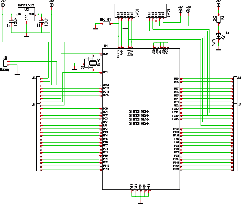
This is the current revision 1.0 of the Rx breakout board. I am trying to find a decent way to display schematics, but the EDA I use is a bit limited in that respect. I am not going to mention what I use because I intend to change that to an open source EDA soon.
Standard SWD Adapter
![]()
This SWD Adapter was created to avoid the need for 2.54 pitch connectors on the boards and to have a standard way of supporting a debug environment with the mini version of ST-Link v2.
The form factor above is made narrow to allow it to be connected to a Hat that is in the middle of a mounted stack. The square version below is the same with a different form factor. These are PCB’s with two connectors that can be soldiered for hand, so they are designed to be dead cheap in volume and will be adapted to various boards.
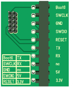
I have used this for a while myself and it makes development on these boards a lot easier. The standard uses 10 pins, but keep in mind that only 4 of those (SWCLK, GND,SWDIO and RESET) are required. 5V/3.3V is just added for convenience. The serial port is nice, but might need to be dropped on some boards.
STM32FxxxRx breakout board
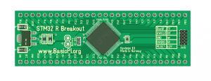 This is mostly for my own usage. I have a strong preference for wiring and testing on bread boards before I order PCB’s. Sometimes it saves you 2-3 extra rounds to be able to do simple concept testing. I have plenty of breakout boards with STM32, but I fancied my own with my own SWD connector etc. For now I am using the first GPIO Hat’s for Zero more on breadboards they are not designed for than on the Zero. It only have components on one side using a two layer PCB, so this is designed to be cheap.
This breakout will work for STM32F103Rx, STM32F105Rx, STM32F107Rx and STM32F405Rx. It might work for others as well, but I have not checked yet.
Small BLDC Motor Controller
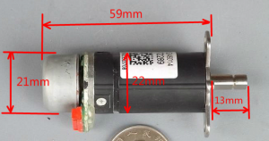
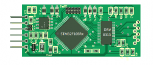
It’s only 20 by 50 mm and my most painful PCB so far. It will run a BLDC motor with up to 2-3A in peaks, 1,5A in average. As mentioned before this was a draft. I am letting this rest a bit because I was not fully satisfied with the outcome.
What is special with this one is that it supports 3 current sensors, 3 Back EMF sensors, 3 Hall sensors etc. What I am not happy with is the 1,5A limit on the DRV8313. As I routed this I felt more and more that DRV8313 ended up as a bottleneck in the middle of the PCB and was not helping on the size either because my design add so much ouside the driver chip itself.
I am considering several options – one is to use SO8 size gate drivers and FET’s. This will require 6 SO8 chips, but I believe they will improve routing and the current I can get out of this solution. The small motor above will only require 0,5A, but it would be nice to have a CAN-X controlled ESC capable for larger motors. I believe we should be able to get 5-10A out.
A second option is to use DRV8301. This has the advantage that DRV8301 contain a separate Buck converter for the MCU with 1,5A available. I do however fear that this will be difficult without increasing the size of the controller.
Again – work in progress. I will be back on this and other motor controllers later.
Raspberry PI Hat’s
I have drafted a few Hat’s so I am adding an overview just to move content into the new blog.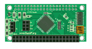
Zero GPIO was my first Hat. This is the new, revised version that I have not ordered yet. I am waiting to verify SPI interface before I order new Hat’s. For the Zero I actually also need to get a Zero as I don’t have one yet. Out of Stock they still are after 6 months.
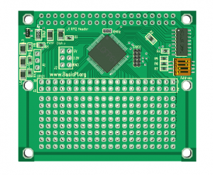
I also added a full size version of the GPIO Hat with a proto-typing area.
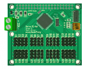
Another Hat in both Zero and full size version is the Servo Hat’s with 16 and 32 servo connectors. The Zero version uses the STM32F103CB which is 48 pins. The 16 x version will soon be used in a Robot project with 12 servo’s.
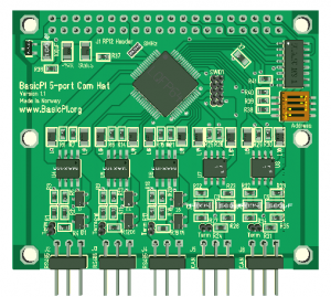
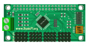
The Hat I am doing software on is the 5 port communication Hat. I need to verify SPI interface with RPI on this. I am using a Raspberry PI 2 for now. Progress on this work can be read through other posts.
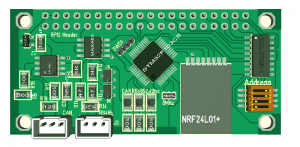
The Zero Com Hat (above) has not been mentioned before. This 3D model is illustrative, but it show a Zero Hat with a RS485, a CAN and a 2.4Ghz NRF24L01+ port. One version of this also uses normal Wifi. The drawback with this hat is the mounting of the NRF24L01+ breakout board. I need to find a way to mount it properly as it will not handle vibration well if mounted as illustrated on this model. This model also still uses the 2.0 pitch connectors that I decided to remove so it is “work in progress”.
New Blog System
I am changing to WorldPress as basis for the blog system since it offers far more options than the old system. The old blog will still be available until content is replaced. This will also allow us to add more content than just the blog as we move forward.