Early morning planning!
Whenever dealing with applications that will be depending on high performance it is wise to check out bottlenecks asap. This apply to all risk scenarios based on assumptions, simply check them out first because they might force your next step. I have three checkpoints coming up:
(1) Speed of SPI with a Hat involved. I am fairly confident on this due to the nature of SPI.
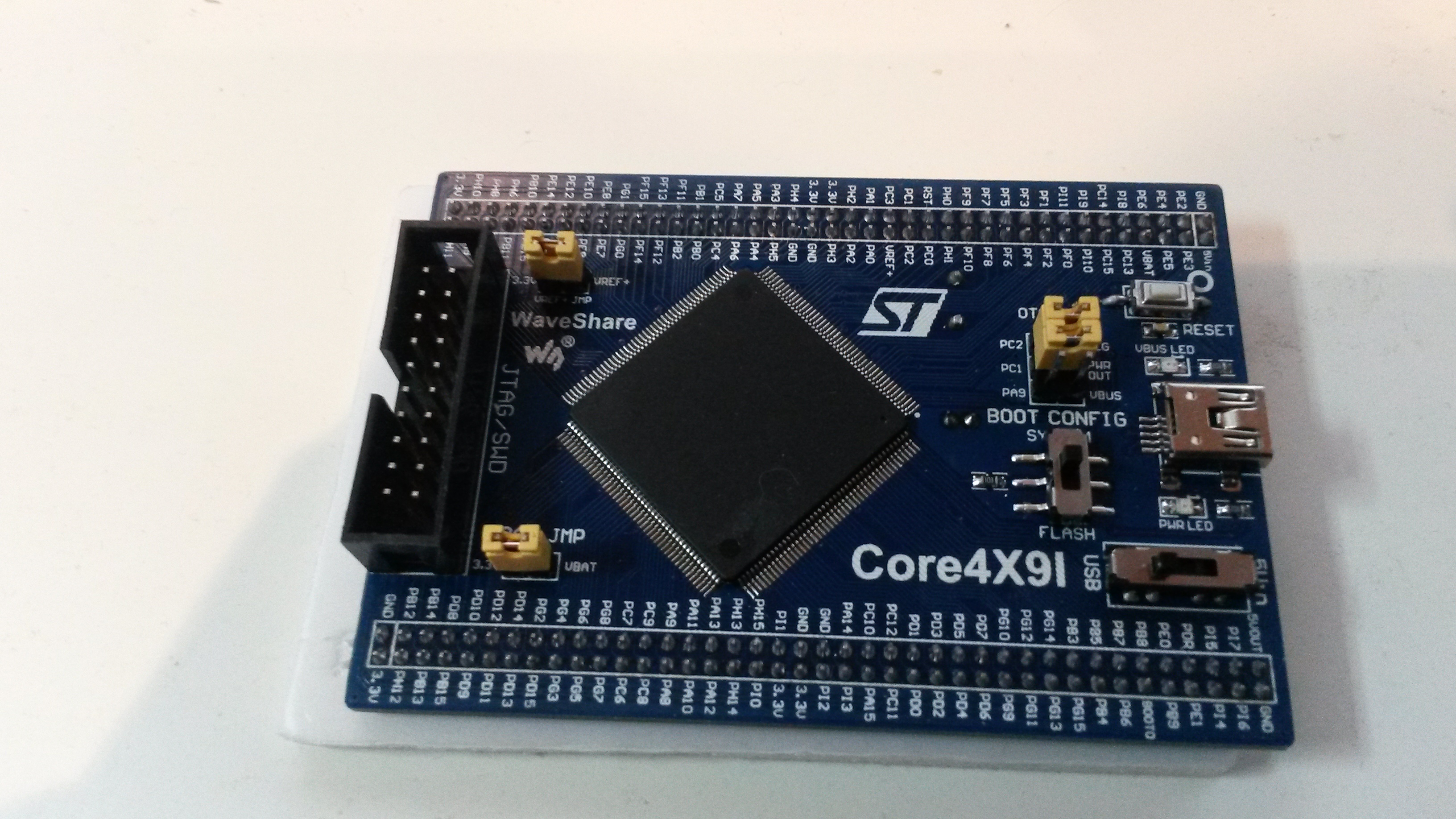
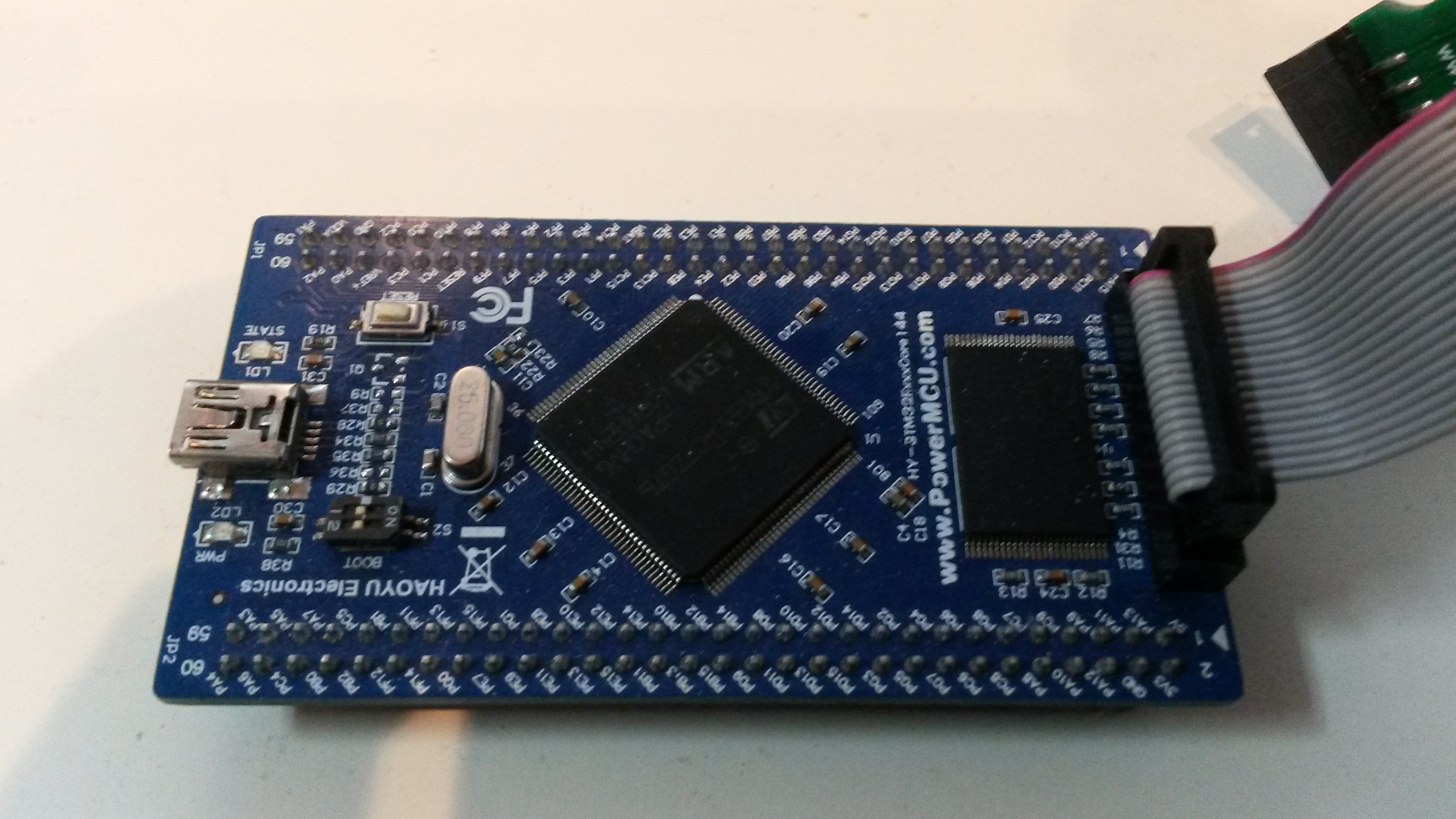
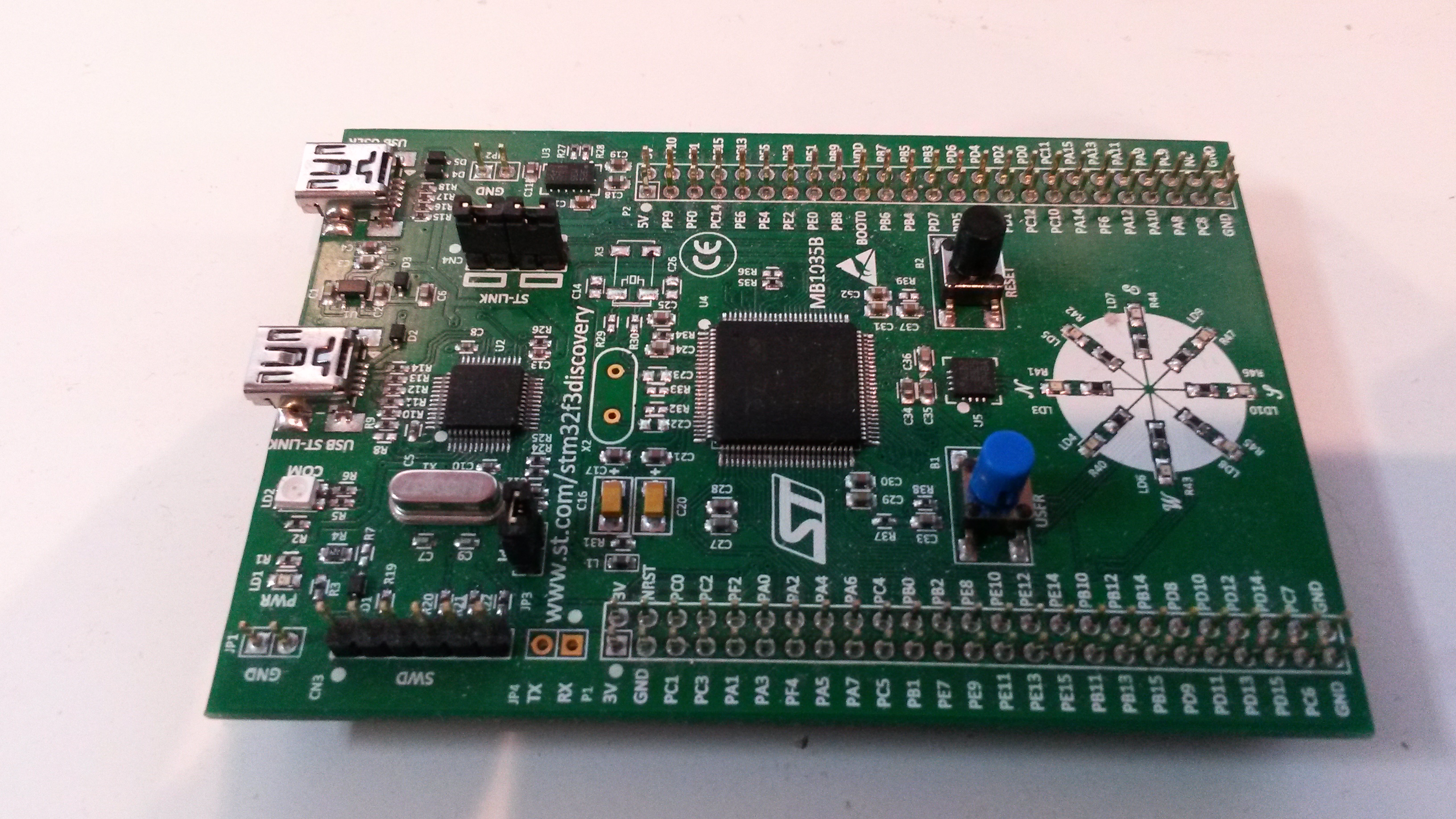
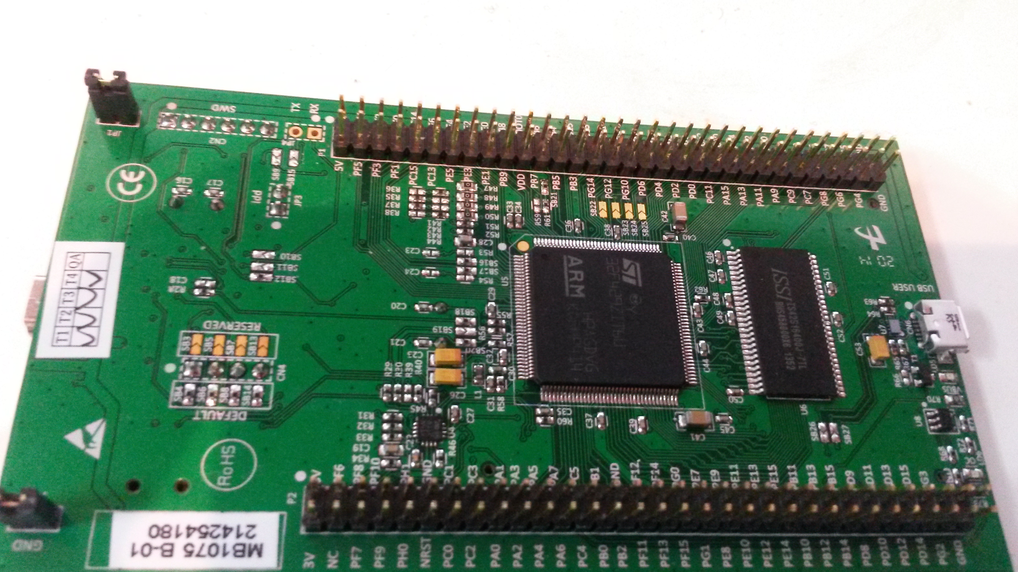
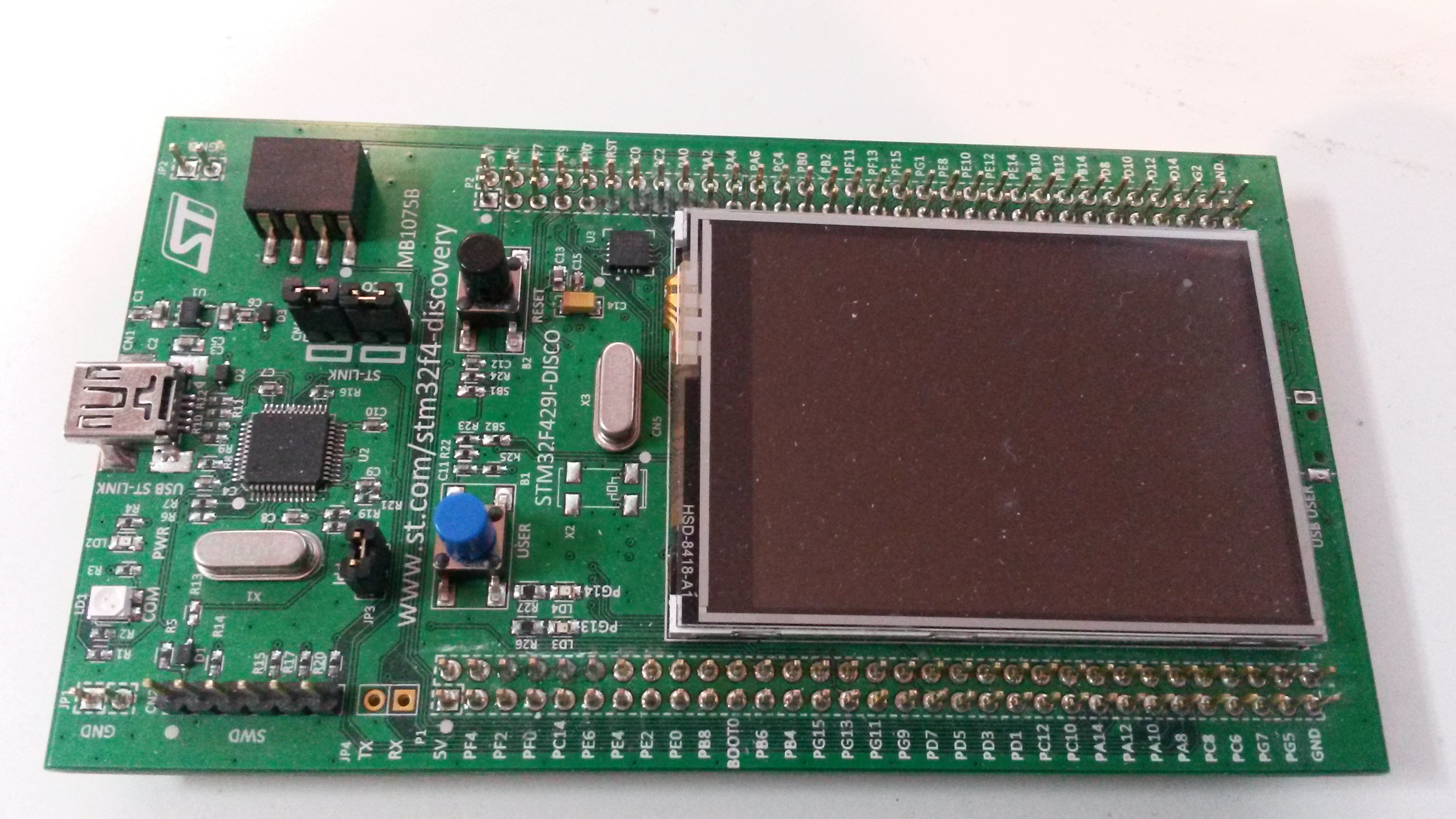
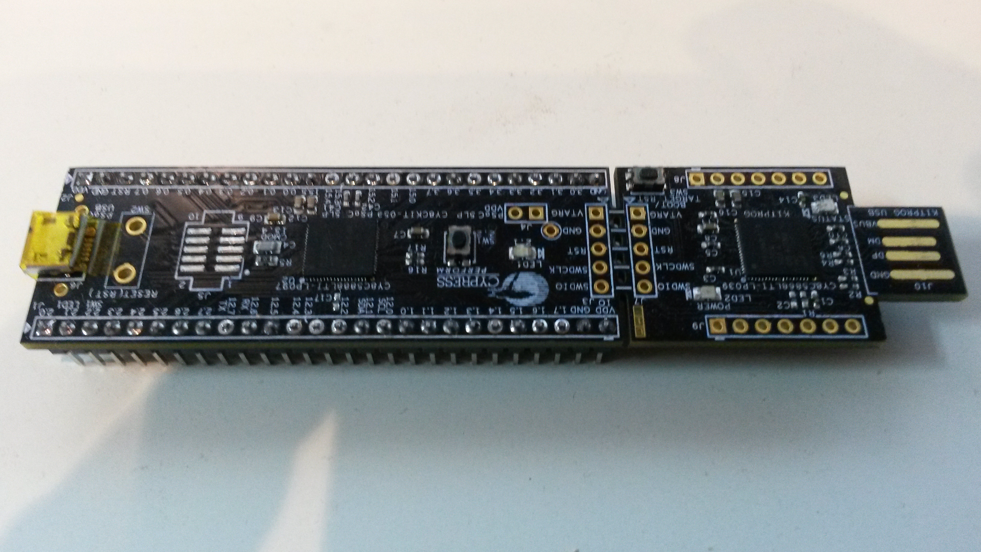
(2) Sampling speed on STM32 and 5LP. I am actually expecting 5LP to be capable of sampling GPIO at a very high frequency, but I might be wrong. Dealing with programmable logic I was hoping for far more than 10Msps, but reading the datasheet I get an impression that this might be a wrong assumption. SPI on a STM32F405 is 42Mhz and GPIO 84Mhz, ADC 2.4Mhz etc. I fail to see similar numbers on the 5LP. I know I am comparing a Cortex M3 with a much faster M4, but I expect a lot of performance from Programmable Logic. The reason for this is because I am hoping I can use the logic to buffer as I sample using the logic’s clock speed like I would have done on a FPGA. But, I realise that I might be in error on this!
(3) Speed of graphics. Raspberry PI is fully capable of full screen animations at 50fps using the GPU’s, but we need to verify that the graphics library we use will support this. I know I can do 50fps on Raspberry PI with GPU’s, but can I do so with the graphics quality I want?
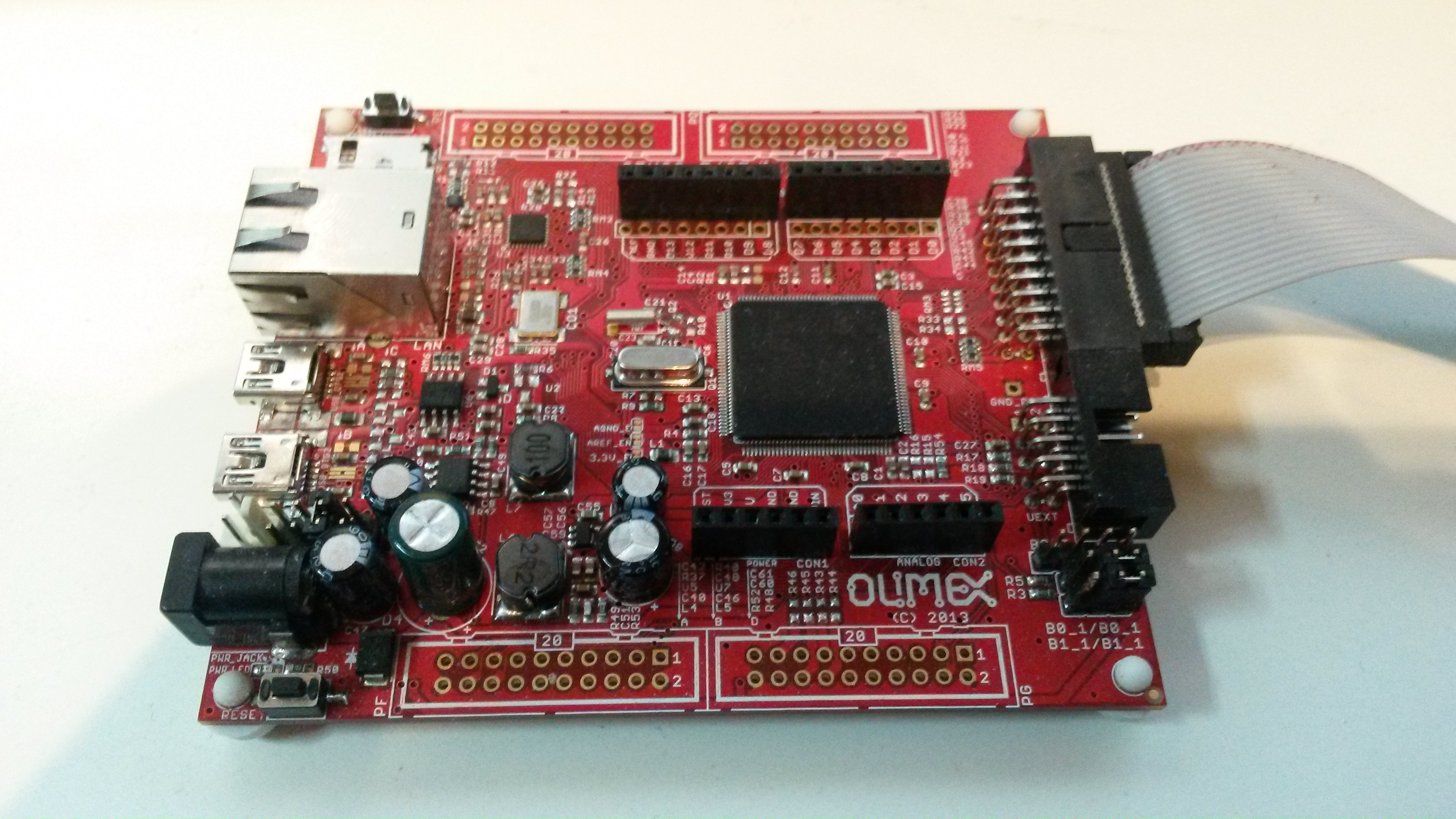
I did a GPIO Hat earlier and due to the pin compatibility on STM32 I can just replace the M3 with a STM32F405 and use this to sample GPIO pins. This will act as a low cost Logic Analyzer. My expectation is that I can sample in a Close Assembly loop, apply smart filter and trigger Logic and use DMA to transfer buffers to Raspberry PI. The sampling speed will depend on MCU speed. 10Mhz means I need a maximum of 16 instructions per sample on a 168Mhz RISC. I know I am on deep water on this, but we will see. I am also curious as to what sampling speed I can achieve with a M3 only. It will be funny to test this regardless.
Doing the same on 5LP is also very easy due to the breadboard friendly dev kit at 10.- USD. Time to do some testing.