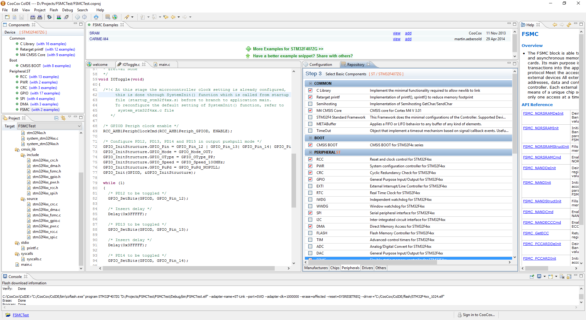
On STM32 (or ARM) I have always used CooCox IDE. This is free and even recommended by ST these days. It is based on Eclipse and quite OK as it integrate properly with full debugger to ST-Link etc.
On STM32 (or ARM) I have always used CooCox IDE. This is free and even recommended by ST these days. It is based on Eclipse and quite OK as it integrate properly with full debugger to ST-Link etc.
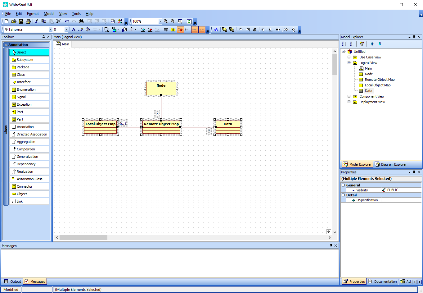
This is a screenshot of WhiteStarUML that I use for simple UML drawings. I actually used to create my own CASE tools in earlier days to achieve a higher level of automation, but those tools are build on MFC and I don’t want to continue using MFC as GUI base since Microsoft is not supporting it seriously.
WhiteStareUML is free, open source and written in Delphi. It is quite ok for high level class diagrams. Code generation on these tools tend to be Limited.
One important part of easyIPC is it’s “repository”, a real-time database that hold all information needed. The repository on devices are very simple and is only a map of objects made available through the interface. Raspberry PI on the other hand will need a repository of all devices as well as a log of data that has been collected. A node hold its own data only and depend on interconnection to other nodes their data. The exception is the dictionary part that need to be on each node so we know what resources we have in our network.
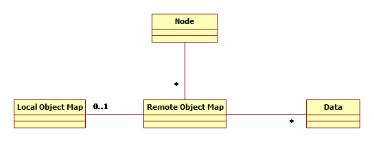
The UML diagram above illustrate the 4 main tables in the repository on Node level. At device level only the Local Object Map is implemented.
Node is a list of main nodes accessible in the system. One of the entries will be “this” node.
Local Object Map is a list of local resources, objects and variables that are available through the interface.
Remote Object Map is the Node’s local info storage about objects. This contain full name, description, PID and other information uploaded from the device at start-up. The Remote Object map can also be loaded/saved locally on the RPI for fast start-up.
Data is a log of data for a selected object/resource.
This is a very early draft so expect some changes as we dig into more details.
Our High Level protocol include a 1 byte message code. The reality is that we can also add PID’s as messages with an object containing several parameters. In fact we talked about reserving ranges of PID’s for special needs. With a 2 byte integer we have 65536 possibilities so if we reserve 0 – 0x7FFF for parameters we can use the ranges above for special needs.
I am thinking about something like this:
As for the main message code we need:
What else? Let’s leave this for now. This is an early draft and we will definitely be adding stuff here as we dig into the details. With both a 1 byte main message code and the possibility to use PID ranges as sub-messages I think we should be well covered. We can even let the PID ranges be message specific if we need to.
One of the challenges dealing with a parameterized system is error handling if only some of the parameters are successfully sent. This is a classic issue for systems using Modbus and CAN that we have solved in easyIPC.
We earlier described techniques using CAN-X/SPI to transfer larger messages using “envelopes”. As an envelope contain it’s own CRC we also have a method to guarantee that a set of parameters arrive complete or not at all. SPI, RS485 and Ethernet will not need the envelope as messages can be rather large and have their own CRC’s.
This means the transaction system is embedded into the communication system as we will either process a complete message or nothing at all.
We briefly discussed Objects in an earlier post related to Begin- and End – Envelope on CAN-X. To just transfer binary data values creates a lot of fuzz with so many devices involved, so we create a generic tagged system known from ASN.1 and very similar to users of Modbus and CANopen etc. This means that all data on a device have an unique 16 bit identifier that we call “Parameter ID” or PID. Every time we send a value we send the PID + the value.
The PID can be a command, a simple variable or a complex object. More important is that only the sender and receiver need to know the PID as it is private for the stream. To do this we need a few global PID’s and we need maintenance messages allowing the device to inform about it’s data repository during start-up. For me as a device developer this means I only need to care about a few common PID’s and the rest can be used as I please regardless of how things are designed on different devices.
This also means that we have a device that will inform the rest of the network about its interface, something that makes plug & play on the level I want possible. Interfacing to this needs to be done through an API where the user access a specific device with a known interface. We can use the same PID technique here but use names to map the PID’s at start. I will return to the API layer later.
I indicated earlier that we should use PID=0 and 1 for the envelope. I am actually reconsidering to move the fixed PID’s into the 60,000 ++ area because if I am on a device it would be efficient if my PID also was an index into my local object map. But, I can still do that if I just subtract an offset.
Different versions of the same device might include changes in the PID array. And some applications might prefer a fixed PID array so they can be coded directly without supporting the more complex plug & play. I need to think about this one because I am not sure I want to take it into consideration at all. It is probably better to create fixed map’s in the API than complicate the devices if we need this later.
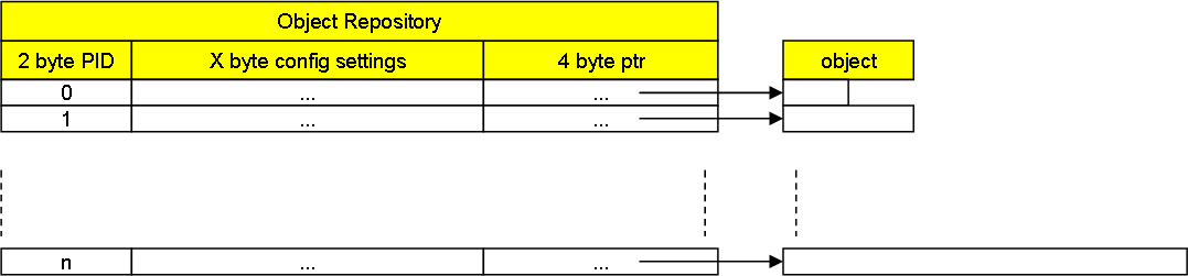
The drawing above illustrate a possible Object Repository on a device. This will typically be set up as a static array initialized at start-up. Each entry point to an actual data value/object in this case. If data is written we look up the repository, fetch the pointer and write the actual data variable. The same value is available top-side through our communication system and the top-side application will see this as if it was a local entity. This technique is called “Remote IO”.
I have a very strong preference for designing a project and then leave the ideas to mature a bit before I start all the hard work on implementation. The reason is simply because we tend to change design as we get deeper into the subject or get new ideas. I do design in haste then I need to, but the results are seldom as good as the ones that have taken their time.
The worst I know are designs decisions taken in haste that the entire teams complain about for years to come. The advantage with the work we do here is that we will take the time we need and get it right. That also includes that we will be slaughtering previous design and ideas without hesitation and with no consideration to political correctness if they come to short. This is much more fun.
easyIPC will be using SmartSPI and CAN-X for transport. I will discuss other transport protocols later. A transport protocol in this context is responsible for transportation of messages in a network from A to B and will cover layer 1 to 5 in the OSI layer.
I will introduce several transport protocols later. We need one for Ethernet and RS485. The RS485 one interest me. I have done Modbus and classic Master/Slave protocols on RS485 in the past, but I want to investigate the option to implement a multi-master Network on RS485. It is actually already been done in protocols like Profibus. The concept is that one device send and once that stop sending the second device will start sending within a few bits timing. The later is a challenge since MCU’s with standard UART’s might not be able to respond in time. If one device do not send the 3rd will start after a delay etc. The main limitation on RS485 is the latency implemented with Master/Slave sequences, so a timed protocol where each device can be active is very interesting. If this can be made to work with standard UART’s it will significantly improve the usability of RS485 networks.
An Ethernet protocol is less of a challenge. I have a design on a XML based protocol I am considering. This was one of the reasons I wrote my own XML parsers back in the days because I needed fast XML encoding/decoding. The drawback with a XML based protocol is bandwidth as it will use 50+% more, but encoding/decoding is actually faster than on a binary protocol. Also to limit the bandwidth usage we can do a few tricks. On Ethernet we can also use more classic protocols like http and web services. But, lets leave that and focus on the higher layer of easyIPC for now.
SDL (Simple DirectMedia Layer) is a 3D graphics engine that uses OpenGL or DirectX depending on platform. To use it is straight forward. You will do a few rectangles on screen with little work.
I am also working with GDI+ on Windows, so I was stunned as to how slow SDL is to start in comparison. I was even more stunned as I was looking for functions to draw circles, arcs and the finer graphics. They simply don’t exist. All I find is a function to do rectangles, point collections, pictures etc.
In simple words you will have to create a proper 2D library on top of this from scratch if you want to use this as a HMI framework. I have actually done similar tasks back in the DOS days so I know that this is a large task to take on.
Don’t take me wrong! Drawing a rude circle is done in a few lines of code. Drawing a high quality graphics one require a bit more work, but doing this with high performance will require a lot of hours.
It will not be my first option!
Using FSMC (Flexible Static Memory Controller) is straight forward as you set up the FSMC I/O and just access the memory directly. What happens is that FSMC Address and Data pins suddenly start clocking on the pins. But, how do I sample ?
I was first looking for some kind of “magical” burst technique in FSMC before it hit me that the one I am looking for is memory to memory DMA. I should be able to use the DMA directly from the I/O pins on the FSMC Data to SPI. The datasheet actually confirms this. This will allow me to sample at the speed of the SPI which in the case of a M4 is 42Mbit/s. The actual sample time will be lower since we need to adapt to an available Raspberry PI speed.
It is a huge difference between sample frequency and the frequency you can monitor. The reason is because you need an absolute minimum of two samples per Hz. The reality is that the more samples you get the more accurate your Logic Analyzer will be. This is why I actually am interested in 100Mhz because it would give me a fairly accurate monitoring capability at 10Mhz and a very high accuracy at 1Mhz. But, it is no way we can transfer 100Msps so we need to do smart filtering and trigger mechanism’s on the MCU.
I can use an external SRAM to sample with larger depth than the internal SRAM will allow me, but as this also uses FSCM we will be down at 50Mhz since the DMA need to do two operations. A second issue is that as we write we will be sending logic on the same pins we use for reading, so we need additional electronics to avoid that.
I was planning to use STM32F405Rx for this because it is a neat 64 pin MCU, but I notice that FSCM is only available on 100 pin and larger. In which case I can as well use the faster STM32F427.
I am however not sure if I want to go forward with this at all. It is doable, but the cost of using these large and expensive MCU’s makes me wonder if it would be better and cheaper to pick up a FPGA. I will however do the testing since I have the chips and the concept interest me.