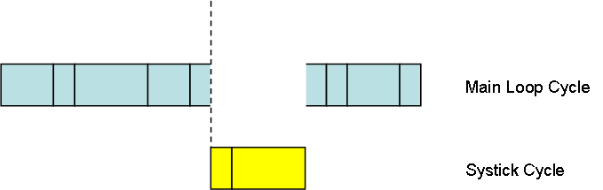
Com Adapter – CH340G

CH340G

I need to test if I can get away with this simple circuit. The only challenge with CH340 is that it’s documentation in English is limited, so it’s a bit difficult to read up on all the pin options. But, I have seen others attempting this so will give it a try. This is CH340 as minimalist as possible with UART on one side and USB on the other.

The reason I like this is quite simple. We bought RS485 adapters for 1.- USD build on these  some time back and now we simply don’t bother with anything else. They simply work to well. They always install correctly on Windows with no fuzz.

Com Adapter – Ethernet Schematics 1.1

W5500 schematics 1_1

Updated the W5500 Ethernet schematics. C9 to C15 present a challenge in PCB routing since I am using 0805 packages. They are supposed to be attached close to each AVDD pin which is a challenge. Also I added the L1 ferrite bead to stop 100Mhz signals from crossing over.

But, I am still thinking that the 8.- USD breakout (below) is a tempting simplification. Particulary since the footprint will be smaller with this. I am also thinking that these breakout boards will even drop in price later.

w5500backside w5500breakout

STM32F303

STM32F303 is a M4 clocking at 72Mhz. It has strong ADC’s and build in op amps as well as 3 motor controllers on the larger chips. It is a very interesting MCU for specialised motor controllers, but have so far been priced in the 10++ USD region. Lately I noticed that CB and CC versions of the MCU are down to 3-4.- USD on AliExpress.

My interest in F303 is limited because I believe MCU’s like F405 and F427 are better choices, but F303 offer the LQFP48 package making it attractive on applications where a LQFP64 is to large. I have so far not considered it because of the cost. I will add veroboard friendly breakout boards for STM32 Cx chips later.

The Rx Version should be able to use my Rx Board. I have mentioned ST’s pin compatibility between MCU’s before. It simply means that if a feature is on both STM32F103CB and STMF303CB they will most likely be available on the same pins though registers and coding might be different. This makes it possible to start With a low end MCU and simply upgrade to get more Flash/SRAM/Speed or extra features.

W5500 breakout

w5500breakout

This is the breakout board version of W5500 available for 10.- USD on AliExpress. I have a few of the more expensive ones for W5200 bought from Wiznet. Using breakout’s like this simplifies the prototyping if you assemble by hand. I also notice that Wiznet support examples for STM32F103 using CoIDE these days.

w5500backside

This Picture show the actual PCB With W5500. Notice the small 0201 Components. The 0805’s look massive in comparison. Usually I can use less Space adding the Electronics directly, but this is an exception. The cost of W5500 and Components are ca 3-4 USD, so 10 USD could be an acceptable trade to make it simpler.

They Reference the Board as “USR-ES1” and looking at Pictures I see a different PCB (see bottom Picture), but I assume the pinout is the same? It exposes SPI, Reset and INT, but it does not expose the PMODE pins.

w5500 breakout pinout

w5500 brk2

This last Picture is from a different Product also marked as USR-ES1. This actually looks like it has been hand-made and not so Nice as the first one.

Lack of PMODE means that the module is wired for auto-negotiation. This can be an issue in robotics because we often have long cables and connectors of various quality. The result can be a 100Mbps that is unstable, so we need a way to force it to 10Mbps to make it stable.

Routing space

routing space

Ok, I underestimated the size and number of passive components around W5500. I was hoping to assemble on only one side, but I either need to increase size or assemble on both sides. This is 0805 components. I can use less space with 0603 and choosing a smaller x-tal. But, 0603 start to get difficult to place manually.

The demo board uses 0201 components, so if I had access to a professional assembly line this would not be an issue at all, but as a hobbyist doing prototypes you need to make these considerations.

USB Adapter Stick

Adapter Stick

I have plenty of RS485 USB sticks that I bought for 1.- USD each. They are great, but I lack the same for CAN. And I lack low cost sticks for CAN Low Speed/Fault Tolerant. The larger com adapter is great, but I will need cheap ones I can afford to loose.

In this I will be using TJA1050, TJA1055, the smallest STM32 (LQFP48), CH340 and a USB connector to make a simple, dumb connection from CAN to USB. The total cost should be something like 5.- USD.


Communication Adapter

comAdp50pros

This is an early draft with only the main components mounted. The schematics are not even close to done yet. I like to place main components straight away to get a look & feel and in many cases I adapt schematics to physical layout. I know some prefer to complete schematics before they start PCB layout, but with modern tools I find it easier to just get the packages and dump them on a PCB. The larger chips often need to be rotated for optimal routing and sometimes you can change components or select a different SPI/UART etc based on what is most optimal.

I have several issues already. The areas at left with the yellow marked isolation space is fine. I have plenty of routing space in that area. The area around W5500 is however tight. An obvious solution would be to swap Wifi and Wired Ethernet. I don’t want to move the led’s up because they will end up under the SWD adapter, but moving W5500 up should work.

I have used ESP-03 simply because I had a pre-made package, but I am thinking of replacing it with ESP-12E. The later is a little larger, but have the same form with legs on the side that will hold the breakout board in place. The NRF breakout have an issue as all legs are on one side. This will make it weak as the other end will tilt up and down and vibration might break it loose. I have seen different solutions for NRF24L01+ so will look into that. The USB is placed in the middle away from the edges because it is held with those 4 large pad’s. These are GND and need extra support to provide mechanical strength to hold the USB as we plug in and out. As mentioned in an earlier post I had issues with this on a different board.

I hope to have the first draft of this ready to order PCB’s tomorrow.

Communication Adapter

Connecting things to a Windows PC is sometimes a bit of a challenge. I am in urgent need of a CAN-X adapter. These things cost and if I add my request for a Wired Ethernet, Wireless Ethernet as well as USB prices start to have several digits. The amount of software needed and the component cost is however not that big a job, so I can as well make one myself for the fun of it.

Communication Adapter2

I will use STM32F405RG as MCU this time. This is an overkill, but I fancy doing something with this small M4 and it only cost 5.- USD.

  • – 32bit ARM M4 168Mhz, 1Mb Flash, 192+4Kb SRAM
  • – BasicPI SWD connector
  • – Issolated RS485
  • – Issolated CAN HS
  • – NRF24L01+
  • – 10/100Mbps Ethernet
  • – Wifi
  • – USB

This is my first Ethernet design and I am cheating big time. The F405 don’t have a Ethernet connector so I am adding a Wiznet W5500 chip. This provide a hardwired TCP/IP stack that we interface to through SPI. The smaller version of this W5100 should be well known for hobby makers.

As for Wireless we use ESP8266. Either ESP-3, ESP-12 or similar. This is a cheap solution that will work well in this case.

I am doing the same trick on USB. This MCU actually have a USB connection, but I am cheating and using a CH340 to get a serial over USB connection. I have used this for years and I never have any fuzz with this one. Programming a serial port is also much easier than programming USB drivers.

The rest of the code is a small router. I will not be doing any clever code on the CAN. I simply want to provide a dumb remote I/O and let software on the PC do the rest.

Rx 1.1 breakout board

It’s not been much activity lately. You can blame the summer and the mess in my garden for that. I want to wire up a few experiments. One is a motor controller based on F405 and the other is a Ethernet controller based on F107. The Rx breakout board is excellent for this as it is vero-board friendly. Looking at my earlier draft I realize that I need to add a few more leds. I want the breakout to be as generic as possible, so using pin’s for leds is a challenge because it means those pins already are used. But, I notice that PC13 and PC14 are located quite handy so I will add a led on those.

Rx Breakout

Rx1_1picture

The first batch will be only 10 PCB’s, but this board will be available in several options. I will make a few assembled boards available for ca 10.- USD + P&P later, but I will also be looking into options to manufacture the boards in higher volumes.