RS-X Network

rsx_switch_p8

This is a simple, passive switch anyone can wire on a vero-board. It just connect 8 ports in parrallell.  “GBA+” is easy to remember and means Ground, B(-), A(+) and Power. You use one port as input and 7 as output in a classic star network.

 The only thing you need in addition are 120 Ohm terminators at the optional place. I introduced 120 Ohm terminators on every module, but I either need to not mount them or add a jumper. The same goes for this circuit as it need a 120Ohm resistor with a jumper.

rs-x-network

The illustration above shows a classic star wiring using these switches. In reality you can cover quite some distance with only passive switches like this. I am not worried about short distances like 10-15 meters, but as the network gets longer we need to take more care.

 Needless to say, this is 50 x 12mm in size and you can use the switch as a cable extender or T point as well. The mounting holes are M2.

Mini SW Draft

mini-sensor-sw-2

The Software on the Mini Sensor Module is outlined above. I need to wrap up a tight RS-X protocol as illustrated earlier. I also need a RTOS ported as well as sensor Logic for each sensor.

DHL11 (or 22) uses a bit-bang protocol. We will use an interrupt on this pin with some timing for decoding. It will send us Humidity and Temperature once per second.

The IR module is connected to an ADC and will measure distance. The Light sensor is also connected to an ADC measuring light.  The last sensor is the temperature sensor on STM32F030F4 itself.

The Data Map tionary is a small module that will map variables in the interface with actual variables in the modules. This is set up as a pre-configured table.

I am a bit concerned about 16Kb Flash, so I have the STM32F042F6 as a fall-back.

32 x Servo hat

rpi-32xservo-hat

This Hat takes advantage of the many pins on a LQPF64 to output a 32 channel servo Hat. 32 channels is a bit of an overkill for most, but the channels can be used for output, digital input and some for analogue input as well. A separate PSU connector for the servo’s must be provided.

The only drawback with this board is that it needs to be on top of a stack due to the Connectors. This was designed some time ago, but I have been holding these Boards back a bit.

Small DC Motor Hat

rpi-4x-small-dc-motor

This is the first draft on a small DC motor Hat. It allows 4 motors to be connected at present. I actually want more motors, so I have to find a smaller connector. I have sufficient space for 8 motors, but the connectors limit me. The challenge is that these 5,08 pitch screw connectors are very handy and not so large in real life – so they are harder to replace than it sounds.

5xCom 1.2

rpi5com1_2

Not that much to write home about, but this is the latest 5 port communication Hat. 

  • Simplified CAN driver.
  • Added double mounting holes for terminals to enable both vertical and horizontal terminals 3P 2.54 and 2P 5.08.
  • Adjusted drilling hole sizes to M2.5, the same as RPI.
  • Adjusted positions more accurate.
  • Increased GPIO header holes a little because they are a bit tight.
  • Tagged CAN and RS485 ports better.
  • Replaced XC6206 with LM1117 to get more 3.3V current available.

Miniature BLDC Motor Controller

motorcontrollerf030drv10983

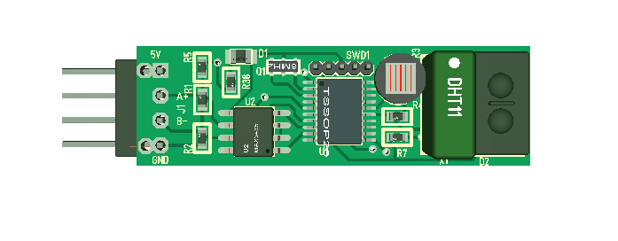
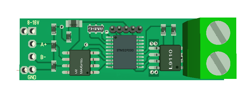
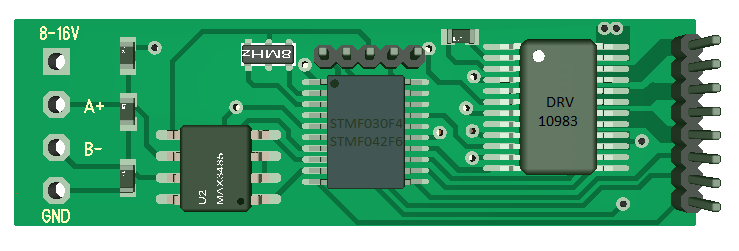
The BLDC Motor Controller above is 40 mm x 12 mm and runs a 3-Phase motor with/without hall sensors up to 2A on 8-16V input. The communication interface is RS485.

  • STM32F030F4 or STM32F042F6 MCU
  • DRV10983 Motor Driver with HEXFET’s.

F030/F042 in TSSOP20 package is among the smallest MCU’s from ST. I literally used every pin on the chip. It is a M0 ticking at 48Mhz and comes with 16Kb/32Kb Flash and 4/6Kb SRAM.

 I actually did not pay this MCU much attention before I received a dev kit and realized that it’s 60% of the size of a LQFP48 package. I just had to try it out.

DRV10983 is a Motor Driver from Texas Instruments. This supports 8-28V, but my regulator is LM1117 supporting only 16V. I am using 3.3V only this time so swapped in MAX3485 as well. DRV10983 have a Bulk Converter supporting 100mA 3.3V, but I need to test if this is sufficient with transmissions on RS485. If it is I will drop the external regulator.

What impressed me with DRV10983 is that it has an easy to route package with GND, Power, U, V and W on double pins. It also have a two pin input driving a 3-phase sinusoidal scheme making it easy to use from any MCU.

  • 180 deg sinusoidal vector algorithm.
  • fault detection.
  • 3 phase motors up to 2A.
  • Analogue/Digital PIN interface.
  • I2C interface.
  • EEPROM to save motor parameters.
  • Bulk Converter with 100mA 3.3V available.
  • Current/BEMF sensors.
  • Over current protection.
  • Temperature protection.
  • Speed Control.
  • Direction Control.
  • Start/Brake Control.
  • Acceleration Control.

Bare over with me if I got some of this wrong, but DRV10983 is worth a look if your looking for an easy path to a miniature BLDC Motor Controller that cover 12-24V.

The STM32F030 or F042 is a bit small for my taste, but don’t worry I will be making a version with F303 and some breakout boards based on some of these drivers.

Note that Hall sensors on this is an optional position Counter only. Hall sensors are depending on a counting mechanism and I hope I can get the timers to do this. The input lines for Hall can also be Connected to a resolver. This part is however not Critical for running the motor.

RS485 Timing Protocol 2

rs485-timing-2

In addition to the silence time detection I can actually simplify the protocol by demanding that each device send a EOT (End Of Transmission) sequence. As EOT for 1 is detected by 2 it can start sending or just send it’s own EOT. If we design EOT to be a small message with status we only need to use timing to detect failing devices. In this case timing is less critical and this is basically the same technique we use on SmartSPI.

rs485-xWith 1 byte status byte that would be 10 bytes that on 19200 baud is transmitted in ca 3.8 ms.

  •  AA : Start byte
  • DID: Device ID
  • SID : Stream ID
  • MID: Message ID
  • SEQ: Sequence Number
  • DL: Data length
  • CRC : 16 bit checksum

RS485 Timing Protocol

One of the challenges with classic RS485 is that we use Master/Slave protocol that introduce a lot of waiting latency. We simply use most of the bandwith waiting. I want to try implementing a timing protocol as illustrated below:

rs485-timing-protocol

This is only an idea at present, but I believe it is doable with a STM32 So I will do a proof of concept for it next. The objective is to implement a multi-master protocol where all devices can be active without killing bandwidth or CPU usage.

The concept is quite simple. We listen on the port and as soon as we detect a 4ms silence we start sending using a scheme where device 2 send after 4ms, device 3 after 5 etc. I assume I need 2-3 ms to differ devices and a way to detect collisions? We will see.