32 x Servo hat

rpi-32xservo-hat

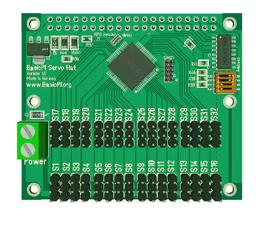
This Hat takes advantage of the many pins on a LQPF64 to output a 32 channel servo Hat. 32 channels is a bit of an overkill for most, but the channels can be used for output, digital input and some for analogue input as well. A separate PSU connector for the servo’s must be provided.

The only drawback with this board is that it needs to be on top of a stack due to the Connectors. This was designed some time ago, but I have been holding these Boards back a bit.

Small DC Motor Hat

rpi-4x-small-dc-motor

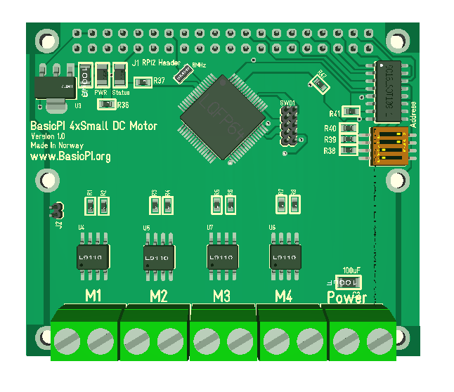
This is the first draft on a small DC motor Hat. It allows 4 motors to be connected at present. I actually want more motors, so I have to find a smaller connector. I have sufficient space for 8 motors, but the connectors limit me. The challenge is that these 5,08 pitch screw connectors are very handy and not so large in real life – so they are harder to replace than it sounds.

5xCom 1.2

rpi5com1_2

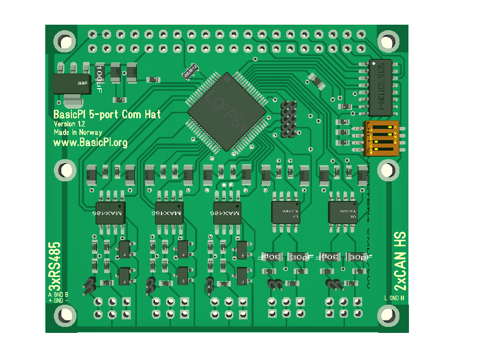
Not that much to write home about, but this is the latest 5 port communication Hat. 

  • Simplified CAN driver.
  • Added double mounting holes for terminals to enable both vertical and horizontal terminals 3P 2.54 and 2P 5.08.
  • Adjusted drilling hole sizes to M2.5, the same as RPI.
  • Adjusted positions more accurate.
  • Increased GPIO header holes a little because they are a bit tight.
  • Tagged CAN and RS485 ports better.
  • Replaced XC6206 with LM1117 to get more 3.3V current available.

Miniature BLDC Motor Controller

motorcontrollerf030drv10983

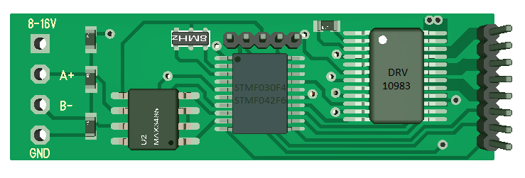
The BLDC Motor Controller above is 40 mm x 12 mm and runs a 3-Phase motor with/without hall sensors up to 2A on 8-16V input. The communication interface is RS485.

  • STM32F030F4 or STM32F042F6 MCU
  • DRV10983 Motor Driver with HEXFET’s.

F030/F042 in TSSOP20 package is among the smallest MCU’s from ST. I literally used every pin on the chip. It is a M0 ticking at 48Mhz and comes with 16Kb/32Kb Flash and 4/6Kb SRAM.

 I actually did not pay this MCU much attention before I received a dev kit and realized that it’s 60% of the size of a LQFP48 package. I just had to try it out.

DRV10983 is a Motor Driver from Texas Instruments. This supports 8-28V, but my regulator is LM1117 supporting only 16V. I am using 3.3V only this time so swapped in MAX3485 as well. DRV10983 have a Bulk Converter supporting 100mA 3.3V, but I need to test if this is sufficient with transmissions on RS485. If it is I will drop the external regulator.

What impressed me with DRV10983 is that it has an easy to route package with GND, Power, U, V and W on double pins. It also have a two pin input driving a 3-phase sinusoidal scheme making it easy to use from any MCU.

  • 180 deg sinusoidal vector algorithm.
  • fault detection.
  • 3 phase motors up to 2A.
  • Analogue/Digital PIN interface.
  • I2C interface.
  • EEPROM to save motor parameters.
  • Bulk Converter with 100mA 3.3V available.
  • Current/BEMF sensors.
  • Over current protection.
  • Temperature protection.
  • Speed Control.
  • Direction Control.
  • Start/Brake Control.
  • Acceleration Control.

Bare over with me if I got some of this wrong, but DRV10983 is worth a look if your looking for an easy path to a miniature BLDC Motor Controller that cover 12-24V.

The STM32F030 or F042 is a bit small for my taste, but don’t worry I will be making a version with F303 and some breakout boards based on some of these drivers.

Note that Hall sensors on this is an optional position Counter only. Hall sensors are depending on a counting mechanism and I hope I can get the timers to do this. The input lines for Hall can also be Connected to a resolver. This part is however not Critical for running the motor.

RS485 Timing Protocol 2

rs485-timing-2

In addition to the silence time detection I can actually simplify the protocol by demanding that each device send a EOT (End Of Transmission) sequence. As EOT for 1 is detected by 2 it can start sending or just send it’s own EOT. If we design EOT to be a small message with status we only need to use timing to detect failing devices. In this case timing is less critical and this is basically the same technique we use on SmartSPI.

rs485-xWith 1 byte status byte that would be 10 bytes that on 19200 baud is transmitted in ca 3.8 ms.

  •  AA : Start byte
  • DID: Device ID
  • SID : Stream ID
  • MID: Message ID
  • SEQ: Sequence Number
  • DL: Data length
  • CRC : 16 bit checksum

RS485 Timing Protocol

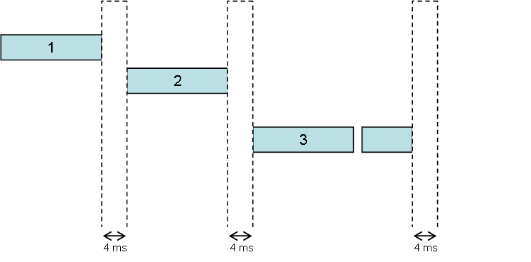
One of the challenges with classic RS485 is that we use Master/Slave protocol that introduce a lot of waiting latency. We simply use most of the bandwith waiting. I want to try implementing a timing protocol as illustrated below:

rs485-timing-protocol

This is only an idea at present, but I believe it is doable with a STM32 So I will do a proof of concept for it next. The objective is to implement a multi-master protocol where all devices can be active without killing bandwidth or CPU usage.

The concept is quite simple. We listen on the port and as soon as we detect a 4ms silence we start sending using a scheme where device 2 send after 4ms, device 3 after 5 etc. I assume I need 2-3 ms to differ devices and a way to detect collisions? We will see.

RTOS part 3 – CLI

A RTOS is at the end of the day only a library intended to assist in making your application, meaning that much of the focus on yX is to be able to adapt to your needs and guarantee portability on source code modules. With yX being able to compile on Linux and Windows this also includes capabilities to test complex module logic in simulated environments like Visual Studio or similar.

 Why do we need a CLI? A CLI (Command Line Interface) is actually easy to create and as we already have a UART on our SWD connector we can put it to some good use. One usage is to support structured printf statements so we can output debug statements as we run. Another usage is a small command interpreter allowing us to communicate with bootloader, kernel and even tasks to assist in debugging and maintenance.

 I don’t expect a memory hungry command line interpreter to run embedded, so the trick I will use is to create a binary command interpreter where we do the interpretation top-side. We don’t need that much only a few commands to support the bootloader and debug support like reading and writing variables. Small things to make life easier.

 Some suggested commands:

  • Read firmware information
  • Download new firmware
  • Restart
  • Peek
  • Poke

RTOS, part 2

yX kernel focus on linear scheduling, meaning that it will run tasks in a time-controlled loop. It is typically used with two cycles, one running in the main loop and a second running on SysTick. Systick on STM32 works well at 1000 times per second using < 1 % CPU load which gives a rather high accuracy in timing.

The trick with this scheme is that our main application will have a stack allocated. As a systick is received the main loop is interrupted and we use the same stack for systick tasks that will finish and reset the stack before the main loop continuous. This technique allows for a much larger scalability in tasks than we otherwise could have achieved.

systick-cycle

Correct timing is very important in embedded systems. yX is capable to do timing down to micro seconds (yS), but the designed target is ms. The timing schemes are:

 Only if signalled

  • Always
  • Timed intervals
  • Average time
  • Idle time only

 yX implement software timers as tasks. You start a SW timer by setting a task to run in lets say 4 seconds using Timed Intervals. This works as a timer that will cause yX to execute that task in 4 seconds time unless it is switched off.

 Queues and events can be implemented similarly by using Signalled task schemes. This scheme will execute the task once for each time it is signalled making it excellent for communication receivers.

Idle time is only possible if we decide how long a cycle is. If we do so we can force the MCU to use fixed idle time length and have tasks that only execute if we have spare time in a cycle.

RTOS, part 1

A RTOS (Real-Time Operating System) library consist of several components that most often are compiled or linked into embedded applications as a library. You don’t really need a RTOS in embedded systems as many are happy running things in a loop (also called Round Robin) and timing things themselves. However, as applications get more complex you end up doing more and more of what I would expect from a RTOS library in your code and at the end it can end up a bit messy. I have a strong preference for using a RTOS and I have a library that I have been using for decades. I ported this to Arduino earlier to run 20+ tasks on a 2Kb SRAM computer.
rtos2

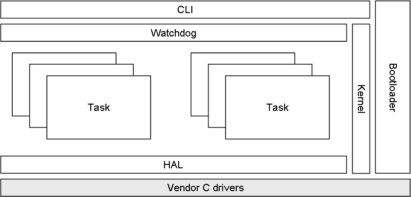
The illustration above show some of the main components in a RTOS package. A bootloader, a kernel, a HAL library, a Watchdog system and CLI (Command Line Interface) is usually included in many packages.

The RTOS I will use is called yX (myx) which stands for micro kernel. The core of yX is as with any other RTOS a kernel that will change from task to task under timed control. yX is however very special in the sense that it is a “linear scheduler” that combines options for actual threading schemes with round robin schemes and offer a very high scalability.

 A linear scheduler focus on continuous usage of resources with minimum of interruptions. One part of this is that we avoid thread shifting and run tasks in sequence (an advanced form of round robin). The second part is that once we thread shift we allow multiple tasks to use the same stack either by using the main stack or by sharing a 2nd stack.

 The result is scalability without compromising CPU load or memory usage. The effect is so good that yX is also used to extend the capabilities of Windows and Linux applications. The later even allow embedded tasks to be moved and run on a host computer, something we will return back to later.

 An embedded Real-Time system have main three concerns:

  • Timing of hard real-time tasks
  • CPU usage
  • Memory usage

Timing requirements are often so hard that they can only be achieved by hardware, an hardware timer or running the task very tight in the main loop. yX can support this directly, but maybe more important is that it can adapt to let the application take over and only focus on support tasks.

One important reason why you actually need a proper RTOS is re-usability of code. The RTSO library with it’s HAL is often the required code needed as infrastructure to make module portable in the first place.
RS485 Timing Protocol

A classic RS485 2-wire network consist of a Master and multiple Slaves. The master query each slave ensuring that only one device communicate at the time. This makes it an easy network to implement, but the bandwidth usage is low due to all the waiting time. The second issue is that a device needing to send an even/alarm simply have to wait.

 Some protocols like Profibus offer a solution to this by using a timing scheme. If device #1 has been silent for n ms device #2 will attempt to communicate etc. This type of schemes have usually required better hardware integration and been unreliable with classic UART/USART ports.

Testing on STM32 will however show that we easily can run a Systick at 1000 times per second giving us a response time of 1ms. We can even run it at 10,000 timer per second with 10% MCU load. This offer an opportunity to respond to events with 1ms accuracy. If we in addition create our serial port so we always will read input we can as well verify if what we send is what we received and detect collisions on the bus.

rs485-schematics

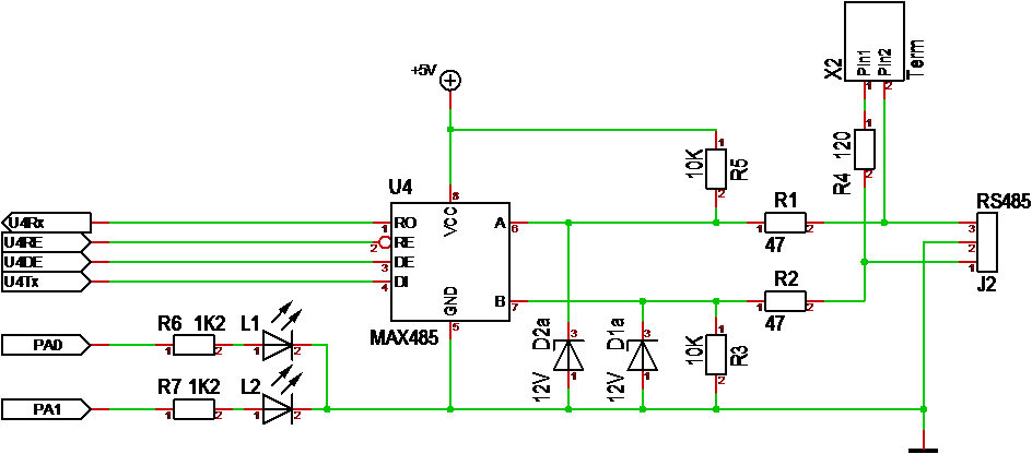
The circuit above shows the modified interface where we control both Read Enable (RE) and Send Enale (DE) from the MCU rather than combining them. The rest of the circuit is rather classic RS485. R4 is the 120 Ohm terminator, R5 and R3 are the bias resistors. R1 and R2 are just shortcut protection and can be replaced with a 0 ohm resistor. D1 and D2 are 12V protection on the line and is optional. L1 and L2 are just leds used to indicate if we are sending/receiving.

The interesting bit about this is that UART/USART interfaces are more commonly available than CAN is and RS485 is easier to wire and get working. If we can overcome the drawbacks of using RS485 we would benefit from a network with the same advantages of CAN, but none of the disadvantages. This will not be doable on all UART’s out there, but I believe STM32 and similar have sufficient juice to manage this without investing into more expensive hardware or compromising MCU availability for other tasks.