Micro Sensor Module

20161120_014457

The 7x PWM module (blue on bottom) worked just fine. I have not used ULN2003 much so eager to test and see how it works. I have not tested the sensor (white on top) yet. The larger DHL11 module is mounted on back because it got a bit tight in the front. Will dig into the bit-bang protocol and analogue readings tomorrow.

Micro DC Motor Controller

20161119_204026

Assembled and tested my Micro DC Motor Controller. Running the test motor on 50ma in the picture. Added a coin to show how small these boards actually are. A few mechanical issues only. The SWD connector is “ok”, but it is a bit close on the MCU. The screw terminal (blue) is almost on top of the LM9110S H-Bridge.

It works perfect, but I have a few spare pins so I will see if I can add current sensor to calculate torque. I can see the current increase as I hold back the motor and I would like to measure that to implement thresholds if the motor run into to high load or stall.

20A ++ Motor Driver

I would like to make a small 3P Motor Controller for 20A and it’s plenty of SO8 size HEXFET’s that can do the job. The challenge is how to get the PCB to support this without going to large. I made this draft that I will try out.

mc-driver-20a

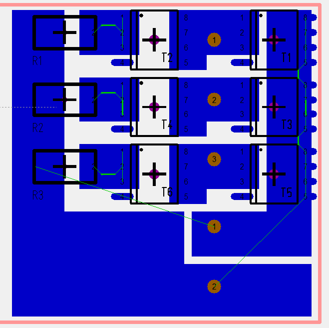
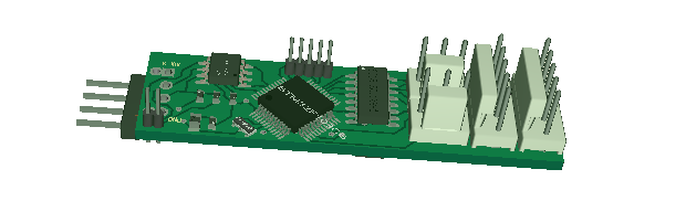
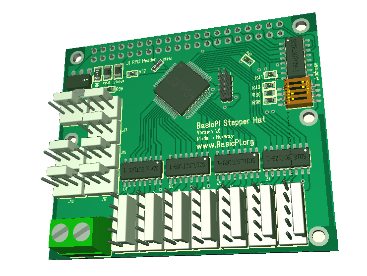
This is a snap from the EDA showing the PCB at the end of a 28mm wide stick. The SO8 HEXFET’s go edge to edge so you can drill a hole to take the output between them. R1, R2 and R3 are current sensors. The picture below show a 3D of the components. I have not completed routing, but I should have plenty of space for the 12 signals (2 x 3 PWM. 3 x BEMF, 3xCurrent Sense) on the other side..

mc-driver-20a-3d

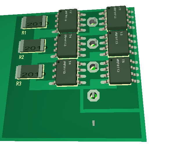
The idea is to mount a flat heatsink on top of the HEXFET’s and shunts.

mc-2a-driver-screw

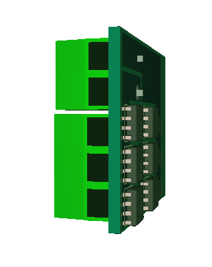
One trick is that I on the back side aligne the holes with 2P and 3P screw connectors to give me the option to use those as well. I will need to give this driver a test to see if I actually can get 20A out of the PCB. I am aware that some of the small ESC’s claim to deliver far more than this, but dissecting a few I found that they claim more current than the datasheet on their HEXFET’s. And they also use inner layers only that is far less efficient than Outer layers. They do however provide a nice array of 12 HEXFET’s with a heatsink. All in all buying an ESC for 6.- USD claiming 30A you have to give guys who created this some credit.

Just for the record, 20A continuous equals much higher motor current’s, but I don’t like overselling. The HEXFET I am using have 170A peak. It will be january before I receive everything I need, but I will be fuzing HEXFET’s and PCB’s to find their limits.

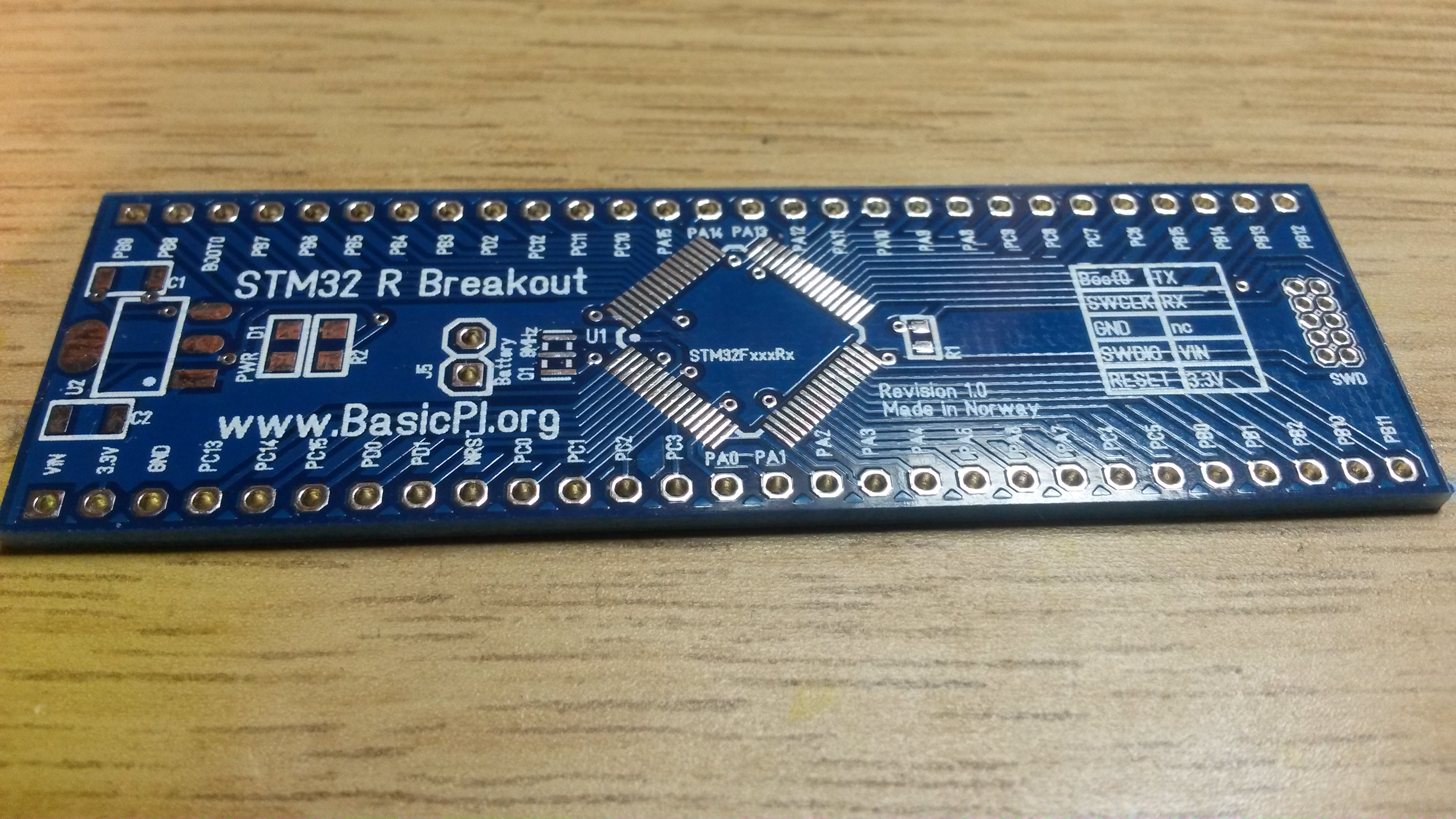
The challenge with current sensors in this is that you need to scale for maximum meaning you get very little on small motors. This is actually also why I fancy making specialized Motor Controllers for small motors, but the STM32F303CB comes in 48 pin package with motor drivers and programmable op amps perfect for this job.

mc-20a-solder-lane

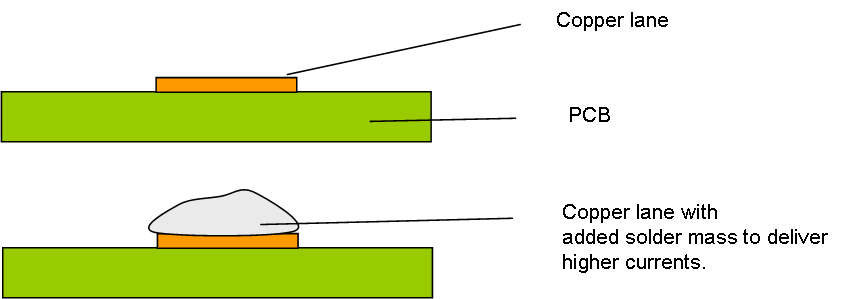
The drawing above shows a normal copper lane (illustrated), but if you look at the PCB layout you will notice that it makes it rather easy to add solder mass to deliver higher currents. This will also be tested to see what we can get out of this design.

Mini dual or 2 axis stepper

minidualstepper

2nd draft of a mini 2 x Stepper module. The connectors are wrong, but they have the same footprint as the ones I need. The size is 55mm x 15mm, but I actually want to draw a mini 3 axis simply because 50 x 50 PCB will be cheaper. Drawing is easy so it’s worth doing to play around with ideas.

Stepper Hat

rpistepperhat

This is the first draft of a 7 x Stepper Motor Hat. It target uni- or bi-polar steppers up to 500mA per phase like the 28BYJ-48. It also have 7 x end-point connectors. Using the ULN2003 as driver it also provide generic PWM and digital ports that can be used as such. The PSU is external and can be up to 50V. The MCU is powered separately from RPI.

DRV10983 Motor Driver

I tend to end up with ST on MCU and TI on motor drivers. This is accidental as I always look for what is out there at a reasonable price and availability. I started with DRV8313, but abandoned it because the PCB ended up to complex for a 1A controller. Looking for a simpler concept I found DRV10983. It has a simple digital/analogue interface to tick a motor. But, it also provides an I2C interface allowing access to the more complex parts of a motor controller.

I like this chip because it is small, deliver 2,5A on 8-28V and allow 2,5A to be easily routed on a PCB. Looking at its datasheet and digging into the I2C interface I must admit that this chip impress me. This is an abstract from the datasheet:

  • 3 Phase sinusoidal algorithm.
  • 8-28V input
  • 2.5A continuous, 3A peak.
  • Build in Hexfet’s
  • Separate 5V or 3.3V PSU (100mA)
  • Single current sensor possible
  • BEMF sensing build in
  • Analogue, Digital or I2C interface
  • Build in EEPROM
  • Current monitoring/protection
  • Temperature protection
  • Voltage monitoring/protection
  • Lock protection if motor stops
  • Speed control on analogue, PWM or I2C
  • Sleep/Standby support for low power
  • Start/Stop ramp-up/ramp down
  • Acceleration control
  • Brake function
  • Anti Voltage Surge (AVS) protection
  • Diagnostics
  • TSSOP24 package With heatpads
  • And much more …

The funny thing is that I wanted a simpler motor controller to get size down and was willing to sacrifice these things since they have limited effect on such small motors.

Bugs Bugs Bugs

Luckily I have a dev board on STMF030F4 that I also can use for verification. The board work (Motor driver not connected), but (1) debug don’t work from CoIDE on this device and (2) the printf() I pulled from the CoIDE repository is unstable. It is the UART driver itself that is unstable, so this is funny – no extra leds, no debug, no serial port I can trust yet… I felt a bit blindfolded for a moment. Progress can be difficult in these cases.

One of the things I like with ST is their documentation is easy to find, once you look up a MCU you find well organized pages with loads of documents. In this case I needed the Errata sheet for the MCU. I notice that many other vendors still have something to learn here.

I also noted another bug while working on this. Using puts() with redirection it sometime compiled in 12Kb. I suspect that gcc tries to be a bit to smart. Normal size is ca 3,5 Kb and this difference matter on a device with only 16Kb Flash.

Regardless, looking into bugs you will find that 95% of the work is to understand “why”, 5% is to fix it. This is why it is so important to invest time into debug/maintenance assistance.

Back to my printf() problem. It suddenly started to work and I don’t understand what fixed it! But, I will ignore this for the time being because I will need to make my own driver regardless to implement RS-X.


Micro 3-Phase Motor Controller

20161110_175027

It is always exiting to receive PCB’s. I am looking forward to work on this one because it is a very small (40 x 12 mm) 3-phase Motor controller. It is designed to communicate using RS-X and control the motor in the background.

micro-3p-motor-controller

The block diagram show the components on the board. Communication is RS485, Motor Algorithm is in this case a matter of ticking speed/direction and configuring the I2C based DRV10983 that also contains the PWM drivers. Have to wait a few more days on DRV10983 and we will try spinning this baby.

STM32F405RG is not pin compatible with other R series

I did earlier state that many of the STM32 series are pin compatible making it easy to scale up. I have to my surprice discovered that this is NOT true for STM32F405Rx versus other R series. I just mounted a F405 on a F103Rx design for testing and it did not work as expected. Paying more attention to the datasheet I realize that I have overlooked that some of the VDD pins have been renamed VCAP1 and VCAP2.

You will instantly notice a short-cut between 3.3V and GND. Well, this was a test and it did it’s purpose even if the outcome was unexpected. I have swapped F103 and F105 before, but this was the first time I checked out F405 before sending off designs using this.

STM32FxxxRx breakout

20161031_231702

This is Revision 1.0 of the R breakout boards. I already made Revision 1.1 before I received these because I realized I needed a few led’s on the board. This board can be used on several R size STM32 MCU’s. The board contain the MCU will all pins available, a SWD connector, PSU and a few leds. Single side assembled only to make it as low cost and simple as possible.