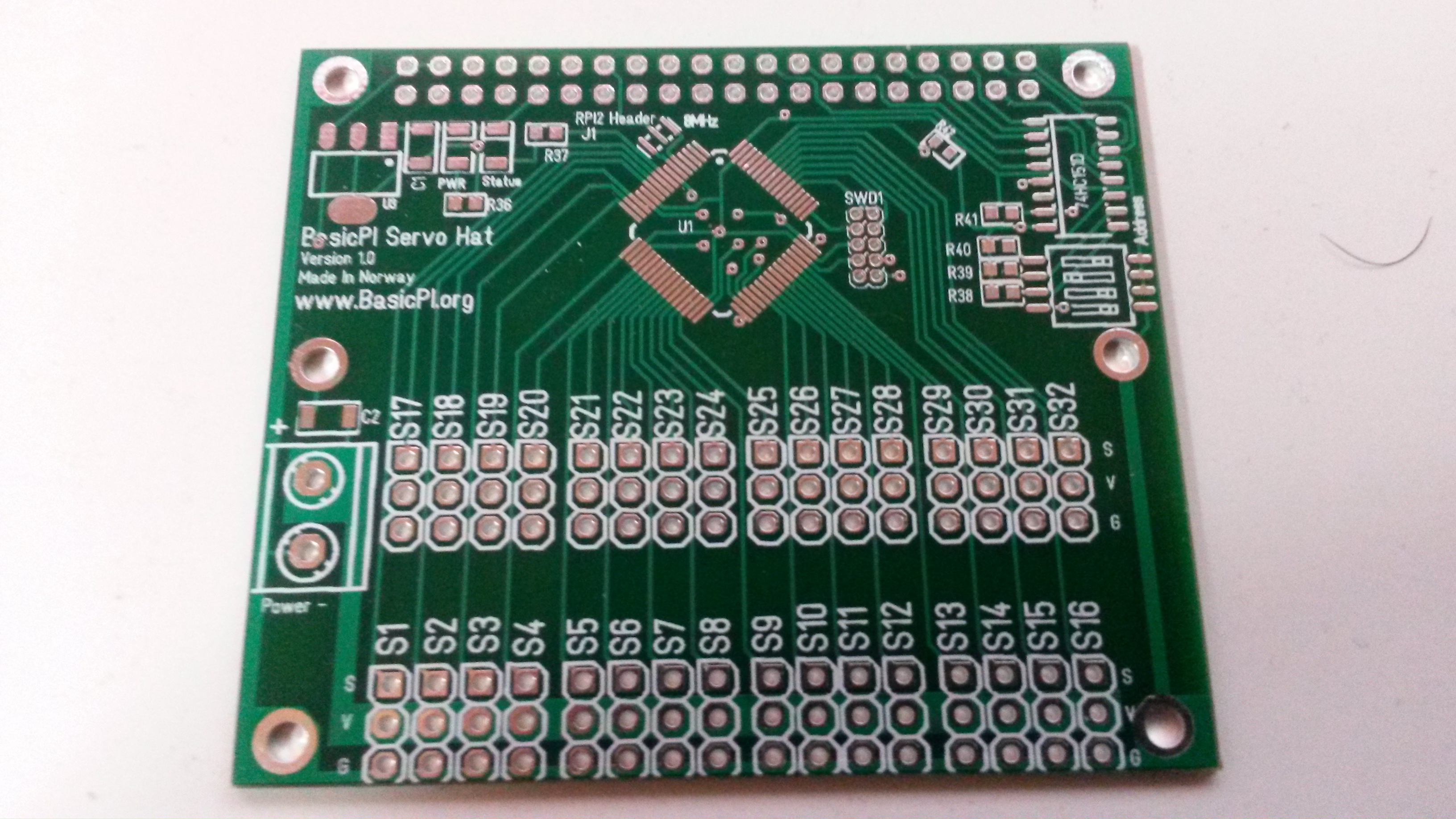
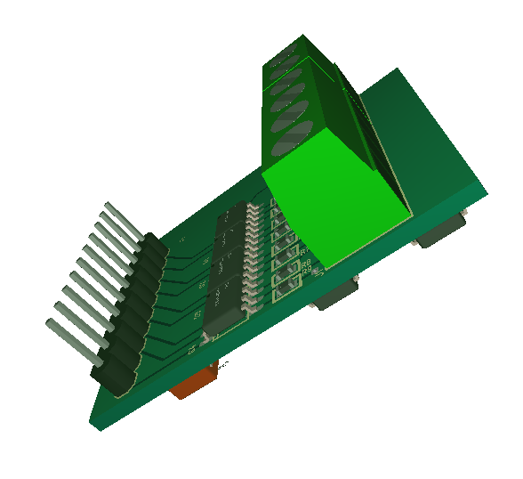
Finally got the PCB for the 32 x Servo Hat. Guess it is time to re-assemble my Robot prototype with the proper control system. I am really pleaced with the mechanical changes I did to the Hat – this is spot on.
3.3V Switched PSU – LMR14208
3.3V PSU is always a challenge on small PCB’s. I tend to end up with linear regulators due to size and cost. They are are great, but regulating from 24V to 3.3V means you use more effect on the regulator than you get out. Sometimes I also need to regulate to 5V and continue to 3.3V. I seriously need to move on to switched PSU’s.
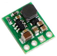
The circuit above is D24V3F3 from POLOLU giving 300mA. It’s 13 x 10mm, but it cost 8.- GBP on ebay and 5,5 USD on hobbytronics.co.uk.
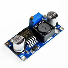
This is a larger one based on LM2596 that can regulate from 1,8 to 36V with 3A or so output. The breakout board can be bought for ca 50 pence on ebay in bulk. I use these a lot because they are great and I can’t even buy the components for that price. 3A is however far more than I need, 300mA is probably ok. An MCU usually tick on 10mA, but transceivers for RS485, Wifi, Ethernet etc tend to use a bit more.
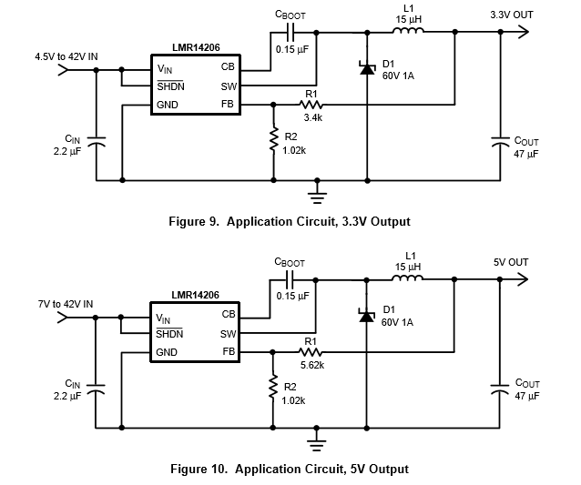
Looking at making a similar circuit myself I found LMR14208 from TI that comes in a thin 6 pin SO package and delivers 600mA. The reference schematics only use 8 components all included handling input voltage up to 42V.
This schematics are from LMR14208 datasheet and it also contains examples for 12V, 15V and 0,8V. I need to find a diode and coil, but it should be very doable to implement a Switched PSU using the same space as the POLOLU one with 600 rather than 300mA. LMR14206 is sadly priced around 1.- USD from the Sources I have, but well – can’t always win.
4 x Half Bridge Driver
I really like routing electronics. It is something relaxing about this task that I find very enjoyable. I started routing on pen & paper single layer some 30+ years ago, so having access to a professional EDA and 2 layers are a dream. I would like to upgrade to 4 layers to get two layers assigned to ground and power to increase signal qualities, but I am amazed with what I get away with on 2 layers.
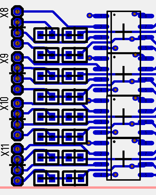
This is the filters, TVS and protections circuitry on the 4 x Half Bridge driver connecting up to the terminal connectors. I decided to make a combined board with MCU and jumper to take out all signals for now. I will simply avoid mounting everything for some of the tests.
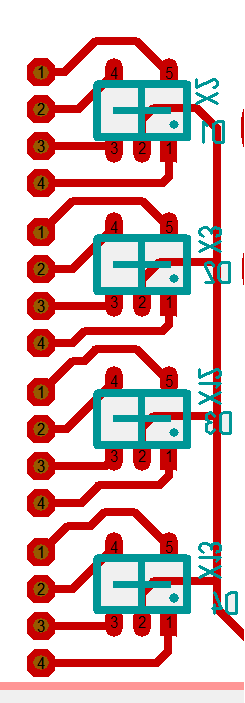
This is the backside of the same Connectors. One of my challenges was space as wanted to add a 6,1V TVS diode on every signal Connected between the driver and the MCU due to the effects involved. I did not thing I would make it, but as I looked at the terminal jumpers that are hole through I realized that I could just attach a 4 x TVS array on the “other layer”.
It don’t look much as it is done, but it actually is quite a bit of work before the rat-nest of wires come nicely together. In this case I changed schematics to adapt it to the PCB. Having terminal Connectors like this between driver and MCU also makes it easy to use these as tes poits connecting a Logic Analyzer/Oscilloscope. I will need an adapter board due to the tight 1.27 Pitch thought – I will be back with a complete board a bit later.
Embedded SSD
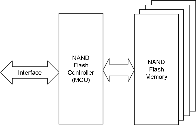
I am toying with the idea to create an Embedded Solid State Disk. The concept is not new or complicated and if you dissect an SSD or USB Memory stick you will find two chips. One is the NAND Flash Controller and the other is the NAND Flash itself.
USB or SATA is not very available in embedded solutions so I would prefer SPI, I2C or UART as interface. The Flash Controller can be a standard MCU with the interface as a 4-6 pin expansion plug allowing a USB Memory size SSD to be connected.
A more classic solution is using a SO8 SPI based EEPROM, FRAM or Flash. They have different characteristics. FRAM is fast and have a high number of re-writes, but it small (typically 128Kb) and actually expensive. A SPI Flash can be 8Mb, but is a bit slower and have a lower number of re-writes.
If we use a decent MCU for this we could also add an intelligent search engine in SW and get the eSSD to act as a database engine capable of processing queries as well as acting as a file server.
We could easily create a eSSD that is 15 x 30mm in size with ca 10.- USD in component cost on a 8Gb “disk”. I do see other people have done similar things, so this is not a new concept. I need to think about this for a while and do some Research.
Current Sensor Design
This is my current sensor. INA210 comes with a fixed gain of 200. Other variants have different gain. I like this concept because it saves me passive components and space on a critical area + the resistors on the chip have better accuracy. R16 and C5 is the low pass filter. INA210 is bi-directional and high side. The Circuit above is low side design since I Mount IN- to ground.
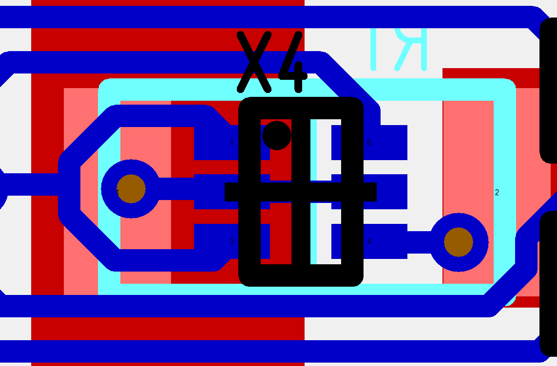
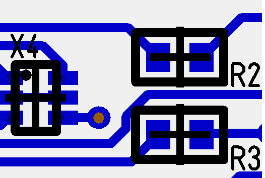
This is the PCB snip. R1 (cyan) is the current shunt. The two place via connectors are the IN+ and IN- measuring the current. I am real happy with this layout because the sensor leads are so short that it will minimize noise introduction. Notice that I am deliberatly placing the place-via on the solder pads on the shunt With virtually no distance to the INA210. The low pass filter is added closer to the MCU/Connector. The layout of this worked out even nicer than I hoped, so I will be curious to test this one to see what I get out on noise vs. signal. I am actually amazed as to how much I get out of a two layer PCB – assuming this Works as expected.
I decided to add 4 current sensors and BEMF sensors because the current sensors will be heated as well and if they fail or give errors (drift) while heated they might cause a more serious error. I basically need to test them as I burn the circuit + it’s cool to have them mounted.
The values I plan is 0.001Ohm shunt and INA210 that gives 200x gain. This giver 0,015V at 15A and 3V out to the ADC while the shunt use 0,225W. I am a bit concerned that the shunt is to small, so might need to increase the shunt and reduce gain to get a better signal – we will see. The drawback of increasing the shunt is that a shunt with 0,002 Ohm uses 0,45W, a shunt with 0,005Ohm 1,1W etc. The effect usage on the shunt need to be keept as low as possible.
I have only been using SMD components for ca 1 year. I started with 1206, continued with 0806 and now I only use 0603. INA210 is SC70-6 body (X4 above) – the two resistors R2 and R3 are 0603 size to give an impression of how small this actually is. I am however not even worried about these anymore – a bit of training and patience does that to you.
New 4 x Half Bridge Driver
A quick evaluation of 3-Phase- and Stepper- Motor Controllers points out the fact that a Stepper Motor only need an extra half bridge driver. Taking our current PCB layout this adds ca 5mm width on the 3-phase driver, so it makes sense combining the two. This also means that I add current sensor and BEMF sensor on all half bridges.
I was a bit undecided on MCU, but adding 2.- USD to use STM32F405RG makes sense in this case. It makes the more advanced software algorithms easier and gives us sufficient space to deal with everything on the MCU.
The challenge I need to find a solution to is the 4th half bridge and how to connect this. 1,2 and 3 connects to Timer1 using the 3-phase interface, but I need to look into the 4th. It is the syncronisation of High and Low with PWM signals that concerns me, but it is possible that I can use Ch1 on Timer8 as the 4th channel.
Some extra features needed are temperature sensors, end stop detectors, encoder and hall support. But, I will look into that later – for now we need to continue and order a Driver breakout for testing.
A short Inventory list:
- 4 x Half Bridge using 8 PWM signals
- 4 x current sensors using 4 ADC signals
- 4 x BEMF sensors using 4 ADC signals
- 1 x temperature sensor using 1 ADC
- 1 x Hall sensor using 3 PWM Input signals
- 1 x Encoder using 1 ADC or PWM Input.
- 2 x end stop using 2 GPIO
- 1 x UART (3 GPIO)
- Status Leds
- And maybe Ethernet …
We are up in 30ich signals on the MCU so a 64 pin should be ok. This will however be a very flexible Controller if we can put it together like this. In fact I am consider making this as 2(3) versions.
- A driver breakout
- A stand-alone board adding Ethernet option.
- A RPI Hat
This will be fun and some hard work!
DRV8711
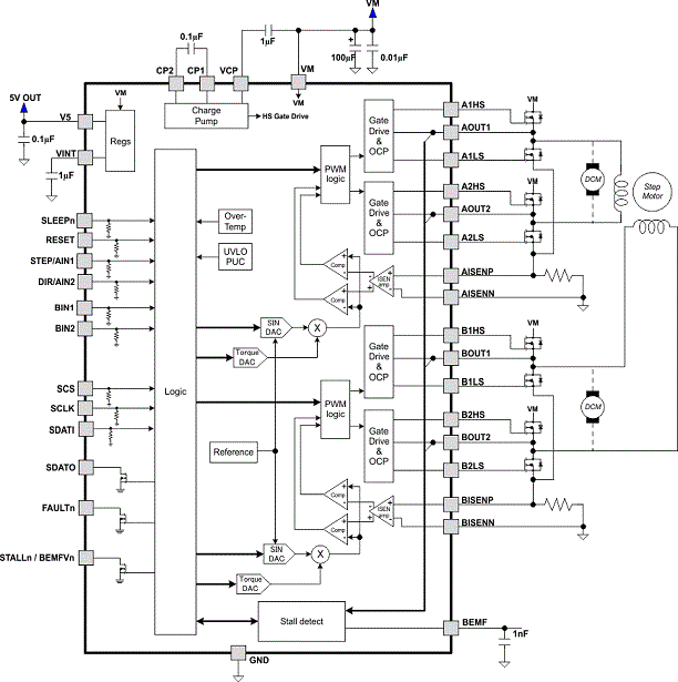
This block diagram is DRV8711, a Stepper Motor Pre-Amplifier from TI. This cost around 5.- USD as samples, so I am not sure I want to bother about it. But, I find it very interesting because it has an easy step/pwm interface as well as a more complex SPI. It adds features like stall detect in logic, current sensors on both phases, BEMF etc.
I am not sure if I want to use these advanced pre-amplifiers or use more complex code. Using discrete half-bridges also enables other options to use them separate. Modern MCU’s are also so powerfully that its not rocket sciense to do the same in software + a bit of electronics. But, well we will see – I will keep an eye on the price and study this one a bit.
Driving a stepper is a rather straight forward + using software you can apply different algorithms. If you use an integrated pre-amplifier like this your locked to the logic implemented by the vendor. It’s ups and downs with everything.
F030 Breakout
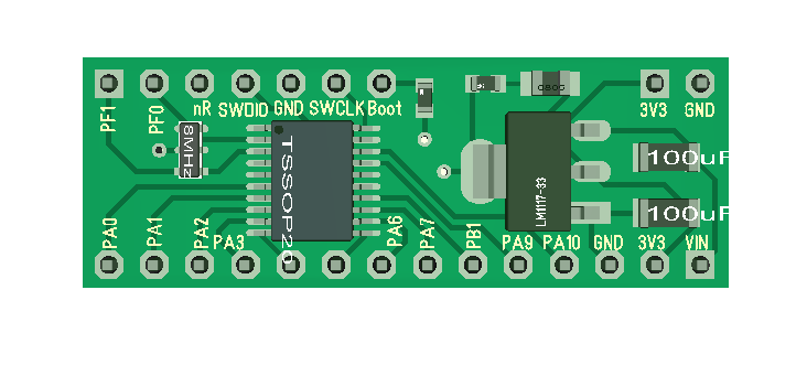
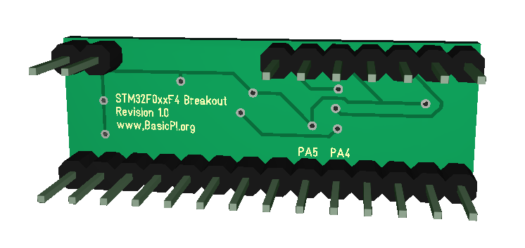
I actually bought a breakout board for STM32F030F4 and discovered that it could not be mounted on a bread-/vero-board. I prefer making proper PCB’s, but I use breakout boards a lot during concept testing. This one is breadboard friendly and can either be mounted standing up or with both sides down. The connector on top contains SWD using 2.54 pitch this time, but the same pin layout as the separate SWD.
The content on the board is a bare minimum consisting of MCU with x-tal, SWD (top) and a 3.3V PSU (AMS1117). All Connectors on the STM32F030F4are available.
PIN Layout is as follows:
| PA0 | PF1 |
| PA1 | PF0 |
| PA2 | nRESET |
| PA3 | SWDIO |
| PA4 | GND |
| PA5 | SWCLK |
| PA6 | BOOT0 |
| PA7 | – |
| PB1 | – |
| PA9 | – |
| PA10 | – |
| GND | – |
| 3,3V | 3,3V |
| VIN (5-16V) | GND |
The benefit of a 2.54 pitch SWD connector is that I avoid the extra breakout board and having the pins to mount thos board flat down if required. The drawback is size and that I loose out on just connecting without to just program the chip. I usually prefer the smaller SWD connector, but this is a special case.
15A Driver Breakout
This is a 4 x half bridge driver with a current sensor. I decided to create a pure driver board because I intend to destroy these in testing to learn it’s actual capacity. I don’t want a MCU mounted on things I expect to be overheated. It is at the same time a bit cool to have the driver step separate for DIY projects. The second layer with the high current PCB lanes are shown below. This is quite small ca 35 x 35mm. The PCB’s take ca 6 weeks so I won’t get them before mid January 2017.
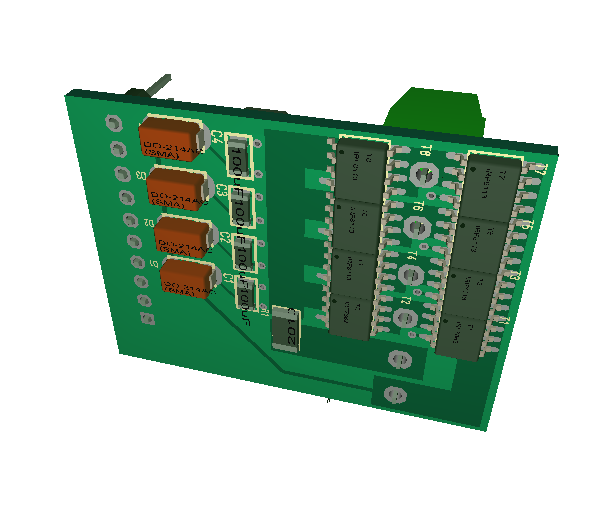 As mentioned before this takes 30V and 17A @ 70 degrees. The datasheet gives higher rating and yes we can draw more for a short time, but I want to know how much I can draw continuously with a heat-sink mounted and keeping an acceptable temperature. I expect the actual capacity to be a bit below the datasheet for the HEXFET’s.
As always – this is a draft. I am considering adding a few things, but will think about that through the weekend.
HEXFET Driver Stage
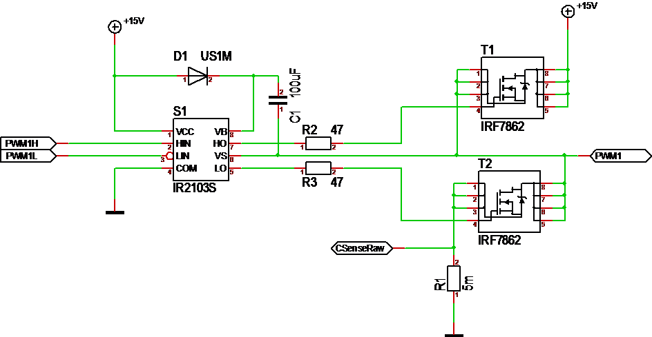
This show a classic HEXFET half-bridge driver. IR2103 takes 3.3V logic in form of PWM and convert it into levels that can drive the HEXFET’s. This is called a Gate Driver. It’s purpose is to deliver signals on correct voltage levels to drive the HEXFET’s. A typical minimum for a gate driver is 10ich Volt. The two HEXFET’s shown are IRF7862 capable of 30V and 17A @ 70 degrees. My target is 12-24V/10A, so this should be sufficient. The pulse drain is 170A and temperature up to 150 degrees.
The nice thing about these SO8 based HEXFET’s is that many of the use the same pin layout. I know of far more capable one’s, but their cost was much higher.
I am a little unsure about HIN/LIN on IR2103. I have a preference of wanting to program everything, but these can be connected to depend on 4 PWM inputs rather than 8.
R1 is the current shunt. This must be feed to an op amp and adjusted a bit. The diagram say 0.005 Ohm, but I was more interested in the correct footprint than the actual value. Measuring currents like this is not straight forward, so I need to experiment a bit with this. In a 3-phase motor we need 2 shunts, but 3 is preferred. In a 2-phase stepper we only need 1 for torque calculations.
