PLC – PowerServo Isolation

I want to add TVS or Photo couplers to the PowerServoe and looking at the PCB lanes above you can see it is only five lanes crossing from left to right and I have plenty of space. All the caps are leftovers from PWM3 and can be partly removed if needed. This one is easy to make fully isolated. The only problem is that the opto couplers require some space and these boards are small… lets see what we can do.

PLC – Power Key

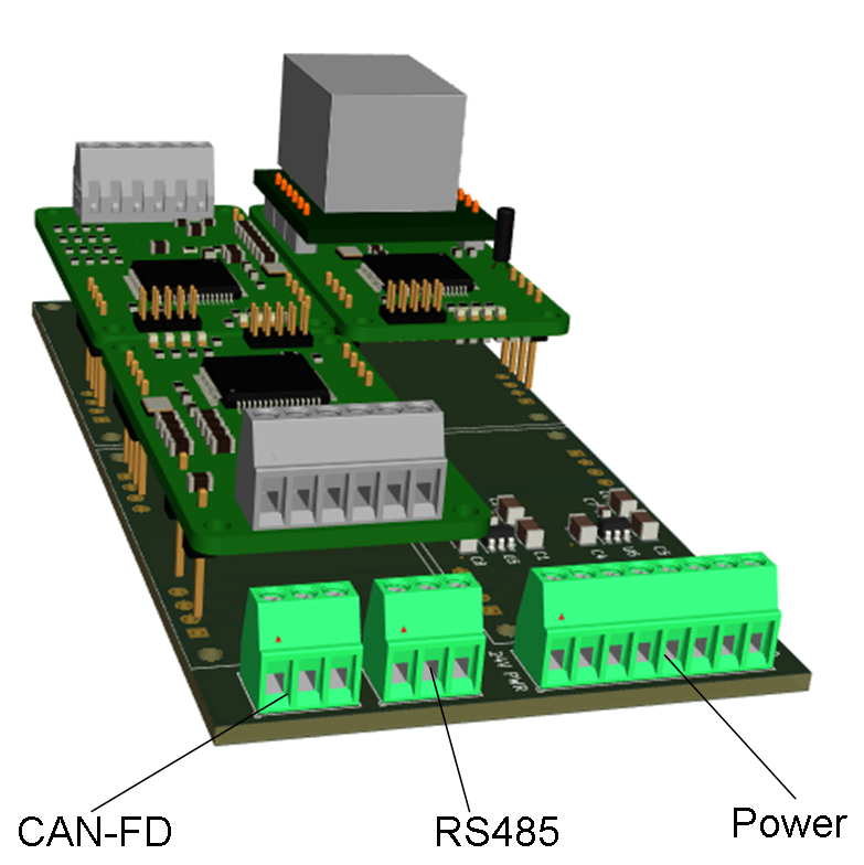
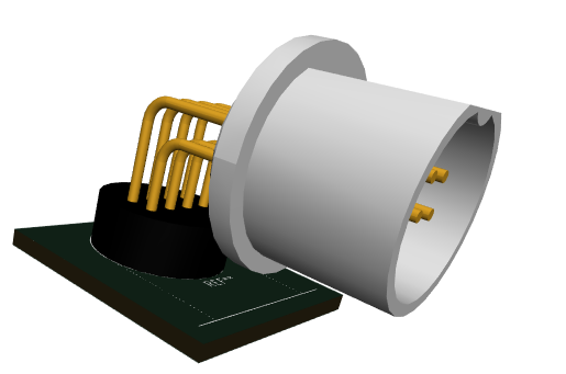
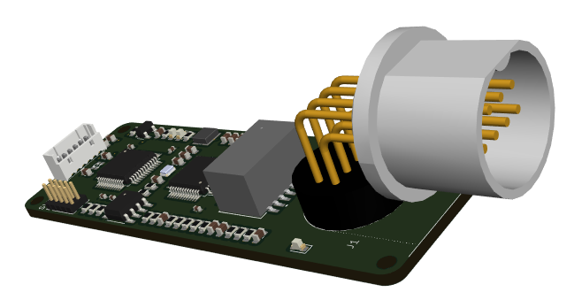
I decided to go with a Power Key, meaning the motherboard will provide 24V, 12V and 6-8V on 3 separate pins. The module then decide what power it need by pin usage as illustrated below. The top image is my Power Servo Controller, while the lower one is PWM3. If a module need to select between 12 and 24V it can provide it’s own jumpers. The objective here is plug & play with minimal options to making errors.


PLC – PowerServo

This is a 2 x Power Servo module I just made based on the PWM3. The circuit is very similar except I removed the DRV8313 and 3 of the current sensors. Controlling a servo is about sending a pulse at 50Hz between 500uS to 1500uS – and I have some 60Kg Servoes that can drain up to 6.5A – so I kept the 6P connector and made 2 power servo connectors that actually can support the currents needed. I need to add TVS (or opto coupler) on the servo signals and this is done – most of the routing was kept from PWM3.

In this draft I have suggested to re-use the 24V pin as 6-8V pin – I will probably modify that because I woudl need jumpers on the motherboard for this and it would be a disaster if I plug in a module on the wrong slot – I kept the capacitor bank from PWM3, but have plenty of space to move that onto. I might even consider opto-couplers on signals on this one.

Current usage on a RDS5160 is rated to 3,5A on 6V and 6,2 at 8.4V – I have ca 10A in total on this module and those header pins will support ca 16A – it is the PCB lanes that limit the currents. But, it is a current sensor on all the power consumers because the real budget will be what the motherboard supports.

Three different modules mounted above – I need to finish the motherboard and the real modules have some text, but looking at PWM3 and teh PowerServo it would be easy to do a mistake – so I will stick to the plan of separate pins for different voltages.

PLC – Module Space Usage

I have just made both these boards, but strugled far more to route the PWM3 board than Ethernet board – looking at the two I got a bit surpriced – On the top board (Ethernet) you can see the same infrastructure components as on the bottom outlined – the top has an extra SPX3819 and SPI-Flash, but notice the difference in density – how much space they occupy. I will order these regardless, but I do notice that on top layer I use ca 60% for MCU and on bottom layer ca 30% for standard ecostructure. Basically I have marginal space for IO as is.


But, keep in mind that this design allows for larger modules – double height and double width as well. It does however question how many of my modules that I can do as 25 x 45 mm size. It also make me consider increasing the minimum module size – that said I am as hesitating to increase as I was to decrease size – I want to give it a try first – collect experience. There will guaranteed be a revision 1.1 of these boards anyway.

One concern is that the W5500 breakout pins get to close to 24V power pin – I will leave that as is, but it might need attention later.

A bigger concern is the need for 24V, 12V and 5V for IO. I have som 60Kg servoes and would like to connect them as well – they need 5 or 12V – so what I am thinking is to extend the 2 pin header with GND, 24V to a 4 pin with GND, 24,12 and 5V – you simply only provide the pins you use. The header pins are good for ca 10A and the PSU is not the modules problem here (motherboard or extern module).

For now I will just add a simple 5V PSU for MCU on the motherboard and use an external PSU as power driver, but I will need all 4 layers to deliever power here because motors and servoes are suckers to power up – servos have a tendency to start and align a position as you power up – and for 12 small servoes I needed ca 10A in peak. Power usage once started is smaller and can be controlled in software.

I am thinking two different servo modules – one for 2x power servoes, and one 6 channel. I might also make a double width module with 16 channels etc – lets see.

Servo and/or Distance TOF interface is my next module(s). The TOF is needed for robotics being able to sence their surroundings and I will start with my own car because I lack distance censors in back and front.

PLC – 3xPWM Finally Done

86 components on 25 x 45 mm – it don’t look like much in 3D, but it was actually quite hard to route even on 4 layers.

  • MCU STM32G491RE
  • DRV8313 for 3 x PWM
  • 4 x Current Sensors
  • 1 x DC Input Sensor
  • 1 x CAN-FD Tranceiver (IPC)
  • 1 x RS485 Tranceiver (IPC)
  • 32Kb FRAM
  • SW controlled terminators
  • 8 – 24V support
  • 300uF capacitance on 24V on-board.

Some of you will recall that I made a similar module before (below). This was 20 x 50mm and 2 layers. It has a 60V DC/DC that worked with a tweak and hall sensors that I never tested – but it was components on one side only. The motor driver worked well – it was CAN here as well. I never used F303, I just used F103 instead. But, it is a 48 pin version of the MCU, No FRAM and no current sensors on this – and it lack capacitanse on-board.  This old board was tested with 50ich Volt, but  I  realized later that  some  of the  capacitors  did  not  hold the speck  – fake  Chinese  crap.  The new  board  will  not  be using components  bought  on AliExpress  – lesson  learned!

Having done an Ethernet Module and a PWM module I want to just get those assembled and evaluate the format as I go. Looking at the module above you can see that is no space for 2 extra SOP8 circuits and 4 current shuts – the circuit above is 40 components, while the new one is 86 components – I literally have no free space on the new one.


PLC – 3 x PWM Module

Showing 3D of the 3 x PWM Module. I had to reduce Voltage to 24V due to capacitors, but 12V or 24V should be ok. I added a 2-pin header for PWM Voltage and a capacitor bank as well as the 4 current sensors. The TSOP28 has a PAD so the middle of the top layer needs to stay clean – I will look into getting 48V supported, but 24V is ok for this little module.


PLC – 4 Module Motherboard

This is the 3D from a 4 module motherboard. I originally planned to use standad 90mm wide boxes, meaning that the motherboard probably needed to be 86 – 88mm wide, but this draft is 91mm wide. It means I will have issues using standard 90mm low cost wide boxes, but 2,5 mm is a lot to cut on each board. The reason for the extra mm is because the motherboard need to leave ca 1 mm between boards otherwise it would be to tight. Board cuts are not that clean or accurate ans 1 mm gap leaves plenty of space for inaccurate fits.

Back to the box issue I am tempted to make my own custom boxes using a 3D printer. I also need some custom cover on the modules and that might cause me to leave extra space for per module, but that is for later. I like my 45 x 25 mm module design, so I hesitate to change it. The issue is that it is easy to remember and if I continue to shrink the board it will leave the format useless. This is actually a very small board as is,

I like the flat-packed, modular design because this allows me to assemble modular systems that is easy to fit on any equipment. The 3D module below show 4 x Ethernet modules mounted since that is the only module I have yet. I have not added headers on the motherboard, but distance between motherboard and module is ca correct. One nice detail here is that adding electronic components on the bottom will shelter them a bit as well. The total width will grow to ca 100mm if I add a box per module. In that case I will have a bottom box for motherboard and a separate top box for each module + dummy for unused slots. That will add 4 mm on each board – 2mm on each side – so the modules would be 49 x 29 on the outside and 100mm wide in total. I need to work on the mechanical design details, but I think this will work out fine. The ethernet module have some extra height due to RJ45 module and it’s headers.

Just adding a differnt view – removed the modules at right and moved in the template module 3D to give a better idea of how a real system might look.

A minor detail here is that I have started to export picture more directly from KiCAD – something that saves me time.

BSA – Using a PLC PWM Module

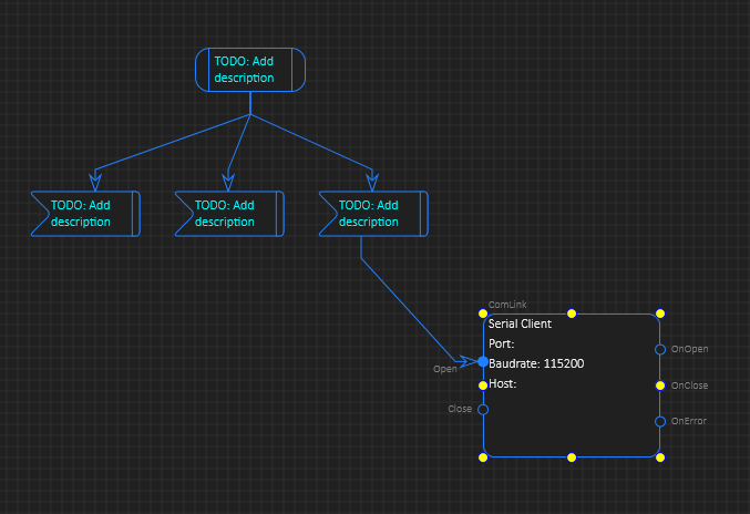
Using a PLC module (or any component) in BSA is straight forward – you simply declare an UML State symbol with the input/output events you need and set this as external with the selected interface protocol and addressing scheme. The protocol can be anything because BSA is after all just a visual specification, so the magic happens in the code generator. If you use a proprietary protocol you will need to implement that and interface it to the selected platform SDK.

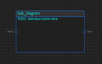
Drawing it like above is physically correct as the message needs to be sent from a top-side (or control unit) to an Ethernet module that forward the message to the PWM using CAN (or RS485), but these are details that we can deal with in config – so I want to see the PWM module only as shown below. How “StartPWM” get to the correct PWM Module is something I deal with in configuration.


You can hard-code physical addresses in an easyIPC network, but a better way is to declare that you have a PWM node with capabilities and ignore the details of how we get the message transported. As you actually configure you system it will look for a PWM module in the network and let you chose which PWM module to use for this purpose. This is also how you replace a PWM module should one break.

I will return to this later as I start using my own system!


PLC – G491RE Template

I will be using a few MCU’s to create PLC Modules, so it makes sence to create a template – starting project for each MCU. The most obvious is STM32G491RE. This template contains MCU, CAN, RS485, Crystal, SWD, Leds, FRAM and PSU condenced as tight as possible towards one side.

The template might change, but the idea is to get a flying start on new modules. As for FRAM and RS485 – if I don’t use them it cost me nothing to not assemble them!

PLC – PWM/Motor Module

DRV8313 is an excellent driver circuit containing 3 separate half h-bridges that can be used as separate PWM drivers, a DC Motor driver or 3-phase motor driver. Delivering 3.5A max in peak and supporting upt to 60V it is excellent for 12V, 24V or 48V systems. I have made a small motor driver on this before and I only need a few passive components connected to the operational Amplifiers in STM32G491 to create low side current sensors. This will be an excelent PLC module and small motor driver.

The drawback with low-side current sensors are that it is difficult to measure individual currents simply because you will not use the low side on solenoid type connections, so high side current sensing is better, but this require additional circuits that drive cost/complexity. So what I will do is to use four current sensors – the forth measure total current on the PWM- (Ground) channels, while the three others measure motor currents. I have 4 operational amplifiers in STM32G491 so this should work fine.

A 6P 2.54 pitch connector fit exactly on the 17mm available on a 25x45mm module, and this allows me to offer 3 PWM+ and 3 PWM- (GND through shunt) connections – for 3 separate signals you use all 6 and I measure current using the 4th sensor, while for a motor you use 2 or 3 PWM’s and I measure current on low side. It is a few issues I need to consider, but this sounds like a great module that will be fun to use.

CAN (or RS485) is great here because I can make this PCB purple or even pay for multiple colors and hang them with LED strings directly on the chirstmas tree. Fun to come 🙂