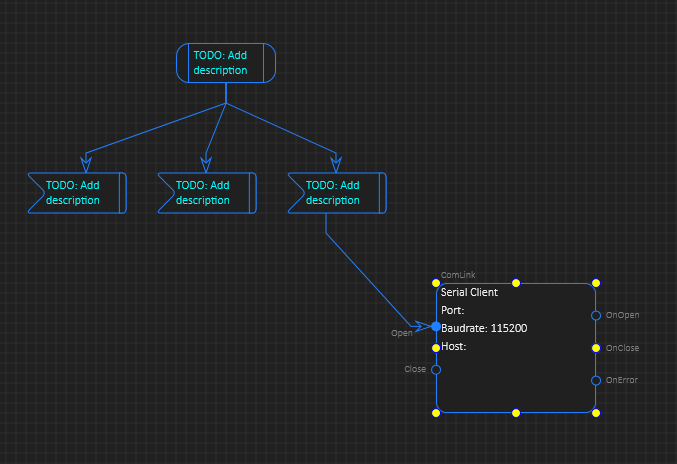
This diagram example consist of two different component types. The PLD state/event symbols have a free connection and atop-down flow, while the ComLink have 5 fixed connections in horisontal path with clear marking on where the events are. To connect you just click on the event circle and drag the mouse to the next symbol – so far, so good. One challenge is the conflict between vertical and horisontal diagrams – in this case I need to move the fixed connections on ComLinq to top/bottom. I also realized that I could delete a flow a bit too easy on ComLink + I sometimes get conflicts beween selecting lines and connection points. These details in BSA are important as they affect your speed of work and will need a bit of work/consideration.
Real Life events have stopped my progress on my own tools a few months, so it is time to ramp up a bit and finish. BSA itself is not that far from being available for early Beta testing, but I need to do a lot on the actual PLC.
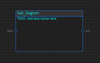
A second, related concern isa recent change I did – I liked the connection points so I forced the sub-diagram to always have them as a test – you now need to modify the diagram or add methods/events in the property list before you connect – you cannot just draw a line (flow) from one component to another and connect ad-hoc anymore. This works fine if you have a fixed number of connections on a pre-made diagram, but I did not like the result. I miss the capability to you draw flow as I go and expect methods and events to be created. But, how do I avoid creating new ones by accident?
It is times then I want fixed number of methods, events and times then I just want to add them as I go. Again – it is related to speed of coding – how fast you get things done. This part of BSA is a bit try and failure. Keep in mind that flow between components is connected to an event and a method with parameters that might need conversion. If you create a new method by accident that also create extra work. A third concern is how to visualize the parameters and parameter conversion.
An event have parameters and a method might have different parameters causing a conversion. This is a lot of hidden information behind a small blue line that we somehow need an efficient way to see and edit. One option is something like the one below – you force a PScript or conversion component if parameters are not 1:1. And if they are 1:1 you can optionally have a list printed associated with the line. One option is to add a symbol on the line so that a conversion box can be hided/expanded because this is also details you don’t always want to see as they will complicate diagrams.
These details are a bit hard to get right as you often have to code an example and test how it is to work with before you decide. I will continue this related to flow lines because they are critical for the tools productivity effect, but I also need to get a first version of this tool on the road soon. In fact I could need 3-4 developers working on this alone. That day will come.
Thanks for reading and I promiss it will be much more material here the next months.


