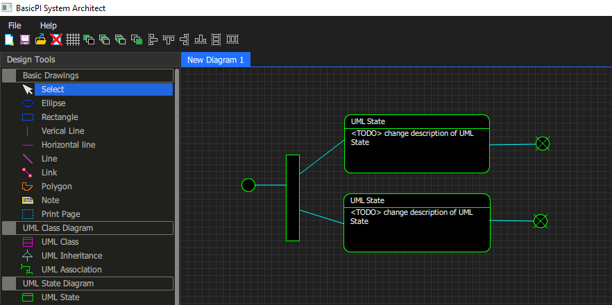
This first picture show a UML State Diagram. I promissed to focus on HMI, but I fancied adding the symbols before I hide these diagrams in the first version.
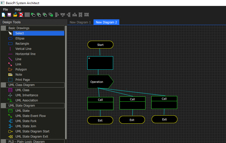
This second picture show a Plain Logic Diagram. I will walk through the interaction between the diagrams and their usage later. As you can see it is only default symbols as I still lack the property editor. I have also started to get all the fiddly images on place so the system starts to look more complete than it actually is. It is still a lot of work outstanding before these diagrams works the way they are supposed to.
I did earlier write about making a HMI Designer and HMI Browser. The designer is what you see above, while the browser will be a run-time engine that execute these applications. But, I will also add code generators for various platforms. First on my mind is a STM32 BSP and Qt/QML BSP, but I also want to look into Node.js and see if I can use that as a backend for a Web Server etc. Lots of options as this is a tool where you create a specification and later deside how you want to execute that specification.
Another task is that I want to add fron-ends to all my electronics boards and start using this to create control systems – lots of fun ahead.

