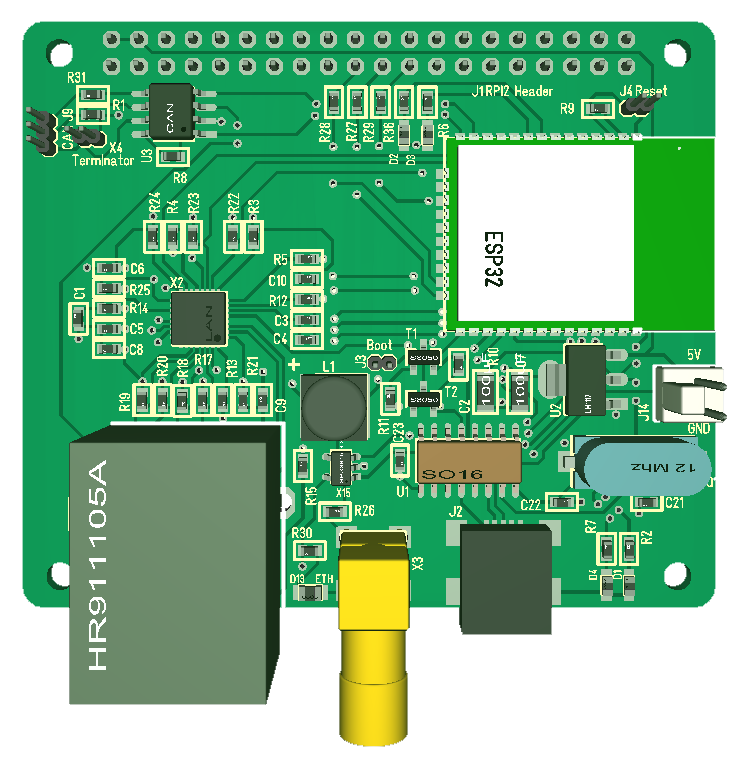
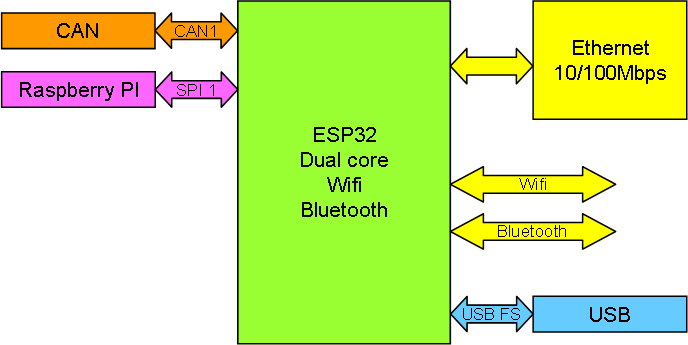
RC1 of the ESP32 based Ethernet/Wifi Hat can be seen above. The module follow the same standards as the STM32 based modules with SPI backbone CAN and USB. The board can fit straight on a Raspberry PI or be combined with any module described in this series. New to this version is that I removed the IO ports of the previous version and added a wired Ethernet option using LAN8710 Transceiver. This is a 10/100Mbs Ethernet and the lwIP stack is already on the ESP32 module. In Effect this gives Wifi, Bluetooth and Ethernet Acces in addition to CAN, SPI and USB.
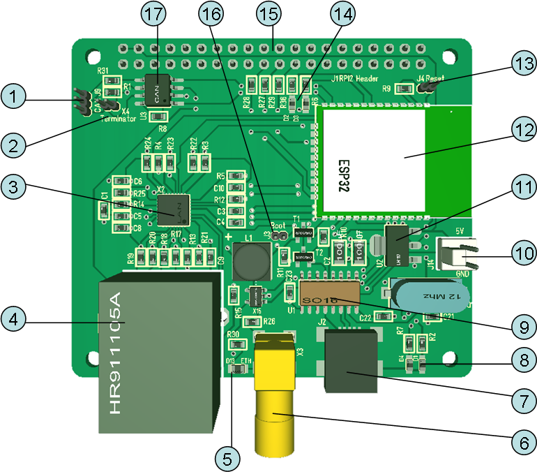
ESP32 have a build in antenna that we still can use, but I added a 2.4Ghz antenna option that can connect to IPEX antenna on some modules. This allows us to use at least 3 different ESP32 modules available on the marked. The 3D model below show the module annotated.
- CAN Connector. The actual connector is a right angle 3-point micro connector. Basically the same as used on all boards.
- Terminator for CAN. If connected add 120Ohm terminator resistor.
- LAN8710
- RJ45 Ethernet with magnets.
- Ethernet power led. This indicate if Ethernet is powered on or not. I use a separate SPX3819 that is controlled by ESP32 enabling me to switch off Ethernet if I want to.
- 2.4Ghz antenna connector for Wifi/Bluetooth.
- USB Mini connector. Needed for programming the module.
- Leds
- CH340G UART to USB. I have used these for a while and I am very happy with their performance.
- External 5V power connector.
- Internal PSU regulator
- ESP32 module.
- Reset connector.
- Leds
- Raspberry PI connector using 5V and SPI.
- Boot connector
- CAN Transceiver.


