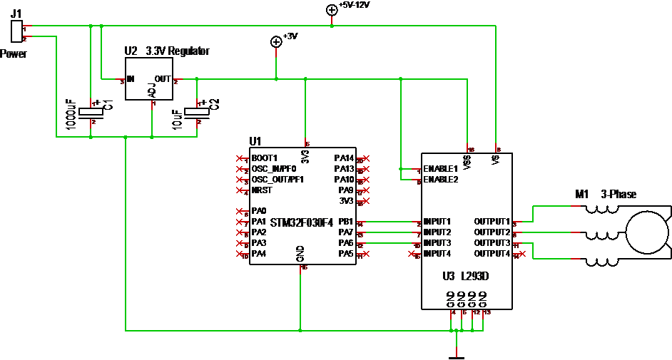
This little circuit is a 5-36V 3-Phase motor driver. In this case I use 3 channels of a classic L293D to output to a small 3-phase motor and run it using a Trapzoidal motor algorithm. I am running L293 on 3.3V, but it will work better on 5V and an Arduino is better for this experiment. MCU’s like 8-bit AVR and PIC have been used for 3-phase controllers for years, and as this example will demonstrate you don’t need much to spin a motor using Trapsoidal or Sinusoidal algorithm’s.
The concept of Trapzoidal is that you pulse each phase in sequence A->B->C and repeat it to turn the motor in one direction. To reverse you do C->B->A. How fast you spin is now your speed as you drive the coils directly by pulsing. You will discover that if you go to fast the motor will not start and if you go to slow t will bump in steps.
To improve the algorithm we take advantage of the 3 coild. Using A create one position, using A+B creates a 2nd and using B creates a 3rd. So we now output PWM to A->A+B->B->B+C->C->C+A and repeat it. You now have the 6 steps of a Trapzoidal algorithm.
            if(forward)
            {
                  Set3Phase(1,1,0,sOn,sOff,speed);
                  Set3Phase(1,0,0,sOn,sOff,speed);
                  Set3Phase(1,0,1,sOn,sOff,speed);
                  Set3Phase(0,0,1,sOn,sOff,speed);
                  Set3Phase(0,1,1,sOn,sOff,speed);
                  Set3Phase(0,1,0,sOn,sOff,speed);
            }
            else
            {
                  Set3Phase(0,1,0,sOn,sOff,speed);
                  Set3Phase(0,1,1,sOn,sOff,speed);
                  Set3Phase(0,0,1,sOn,sOff,speed);
                  Set3Phase(1,0,1,sOn,sOff,speed);
                  Set3Phase(1,0,0,sOn,sOff,speed);
                  Set3Phase(1,1,0,sOn,sOff,speed);
            }
If you drive the motor directly you need to send a PWM with sufficient length & torque to move the rotor. This will vary with input voltage, but start at 5V with 50% PWM duty. I had to use 100% at 5V and 30% at 12V. Once the motor is started you can accelerate it up into speeds.
The drawback with this algorithm is that it has no knowledge of rotor position so the vector we output might be wrong. In most cases it will need ca 1 turn to sync with the rotor.
Trapzoidal algorithm is not used these days because you can as well use the Sinusoidal algorithm as minimum. But, a simple trapzoidal algorithm can be implemented in logic without a MCU involved.
The Sinusoidal version is based on a Sinus curve. While we on Trapsoidal have 6 steps we will on sinusoidal vary PWM duty on A,B and C to create as as many steps as we want.
Keep in mind that a coil act as a filter, so with 5V and 50% duty I am actually outputting 2.5V. By changing PWM duty I can create several more steps to make the motor move smoother. This require a bit more math, but most MCU’s can manage a pre-calculated lookup table etc.
The remaining question is however – where is the rotor? To know this we need to add a sensor. In fact we have 4 different ones that can be used for measuring speed and rotor position.
- BEMF. As we output voltage on 2 coils we can measure the feedback on the 3rd. I have never tried this, but the feedback should tell us something about position.
- Current Sensor means you add a low- or high-side current sensor on each phase and you can use them to calculate rotor position.
- Hall Sensor will give a position signature based on magnetic fields.
- Resolver will give you position.
Knowing the position you can use this to look-up the next entry in Trapsoidal or Sinusoidal algorithm. But, you could also do more advanced math to calculate a perfect 90 Degree vector – this is the FOC algorithm that requires a M3 or faster to be possible.
A lot of my articles dig into the more complex sides of running a 3-phase motor and might give the impression that this is more difficult than it is. So, I advice you to get an Arduino (or whatever), connect a L293 and start spinning a small 5-12V 3-phase motor to see how easy this actually is.
