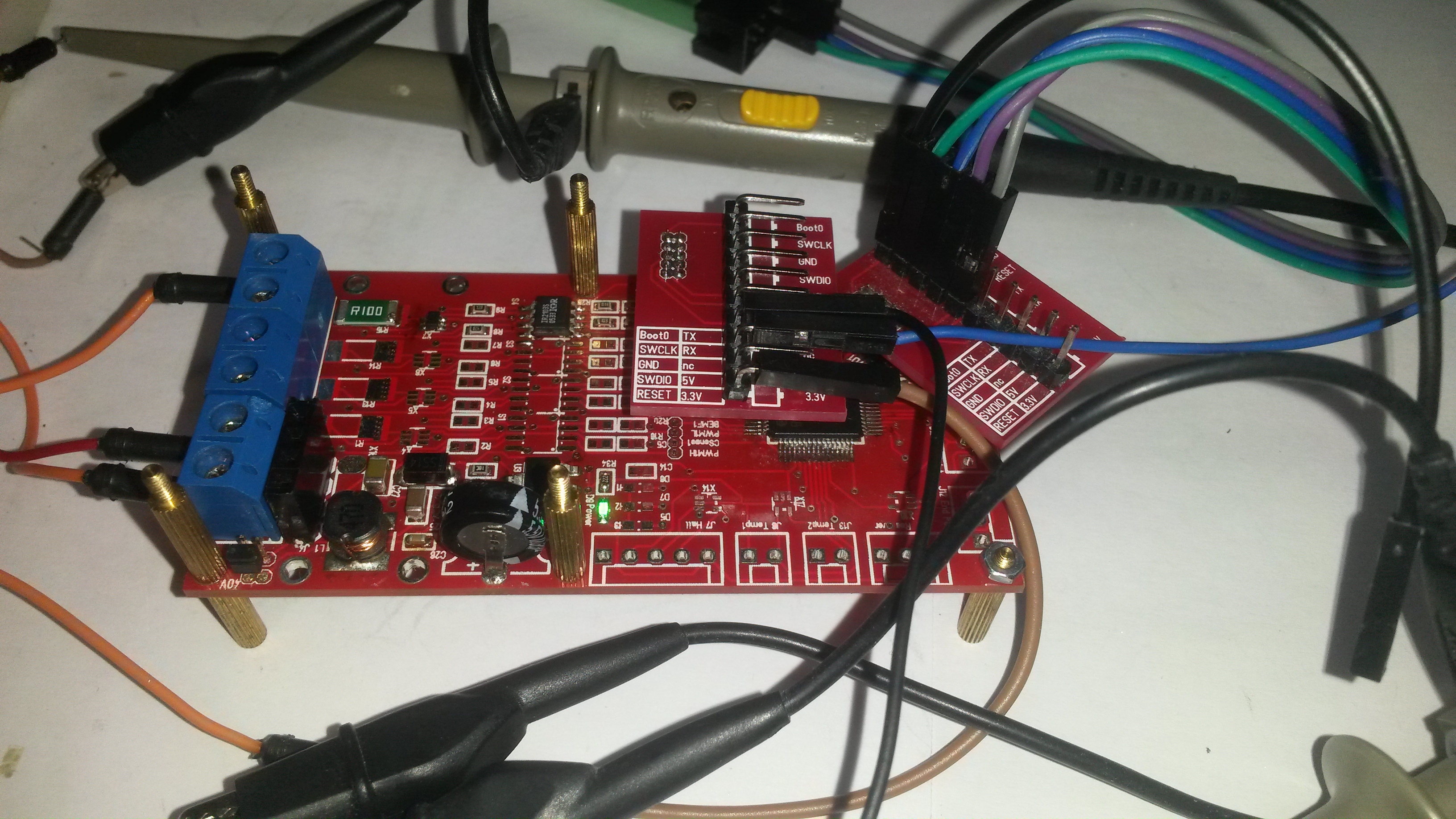
I am so far happy with the MC4X15A PWM channel with the exception of the current sensor. I have 3 more channels to solder up, so I will do the next without the low pass filter for comparison. I did not like the scope pictures, but will be interesting to see what I can do in software.
This picture illustrate some of the challenges involved in scoping. I am using a 2nd SWD adapter to get hold of the 4 pins so I can scope them while testing. As mentioned while I meade this I intend to destroy a few boards to learn the driver limits. I accidentally burned transistors with a shortcut, so will be interesting to see the limit as I add heatsink.
I am also running the MCU at 8Mhz yet. It will be interesting to see what happens as I increase frequency and things get more sensitive as I have a lot of noise at moment. The HEXFET’s have a 30V limit, so if the PSU noise is an issue I will replace the DC/DC with a 78M12. One thing that works well is the supercap. I am surprised of long it keeps the MCU ticking after power-cut and it should do wonders in absorbing spikes and protecting the 3.3V.
One of the next things I will do is to solder up a PWM channel on a separate board and burn it. This test is a bit tricky as I don’t have a Lab PSU to support the test yet.
