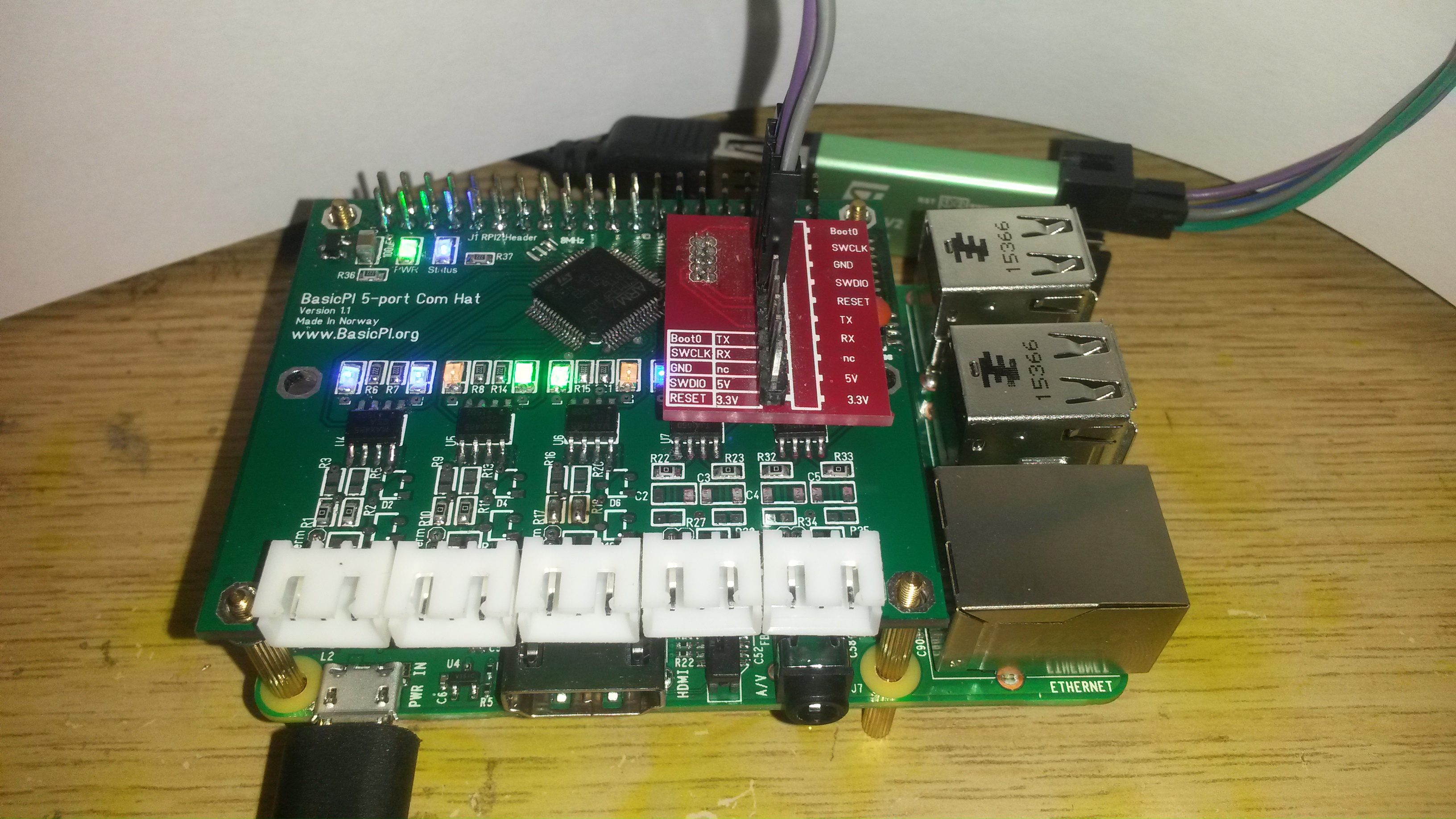
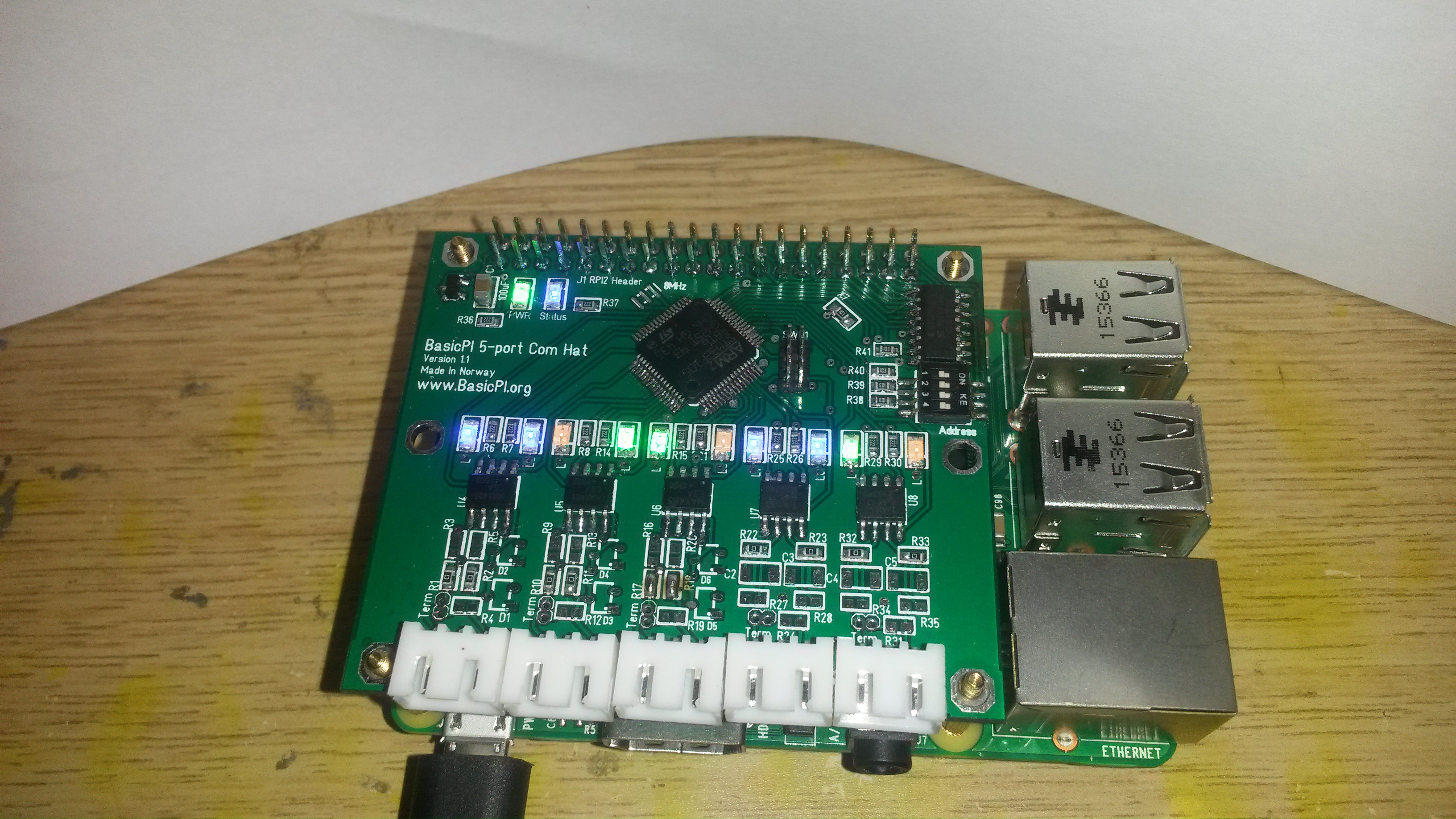
This is a 5 port communication Hat mounted on a Raspberry PI 3. It contains 3 x RS485 and 2 x CAN ports. The design is not new for readers of this blog, but it is actually the first time I assemble rev 1.1 – just before I am about to order rev 1.2.
The colorfully display is because I am using 1206 led’s and saving old parts – all components on this was re-used from rev 1.0 boards. What amused me a bit is that as I mounted the MCU and switched Power on the old test program still worked. I have yet not broken a STM32 by soldering it on/off boards – quite impressive actually.
Functionally this Hat is ok, but mechanically I ordered a few Hat’s before I checked the drilling holes exactly, so rev 1.2 will correct this. I will also replace 0804 and 1206 with 0603 components + 2 leds per port is a bit overkill. I think if I reduce to 1 per port and mount them on the side that is better. Also cleaning up the line driver and replacing the 3P connector with a 4P for RS-X 12V + differential signal. I might have to make this a 2+2 port for that purpose.
I also want to do an experiment. Both CAN and RS485 are differential signaling, so I wonder if I can get RS485 to work with a CAN Tranceiver and what quality it would have? The issue is that if I can do this I can more or less make the 2 CAN ports switchable between CAN & RS485. It is worth a try!

