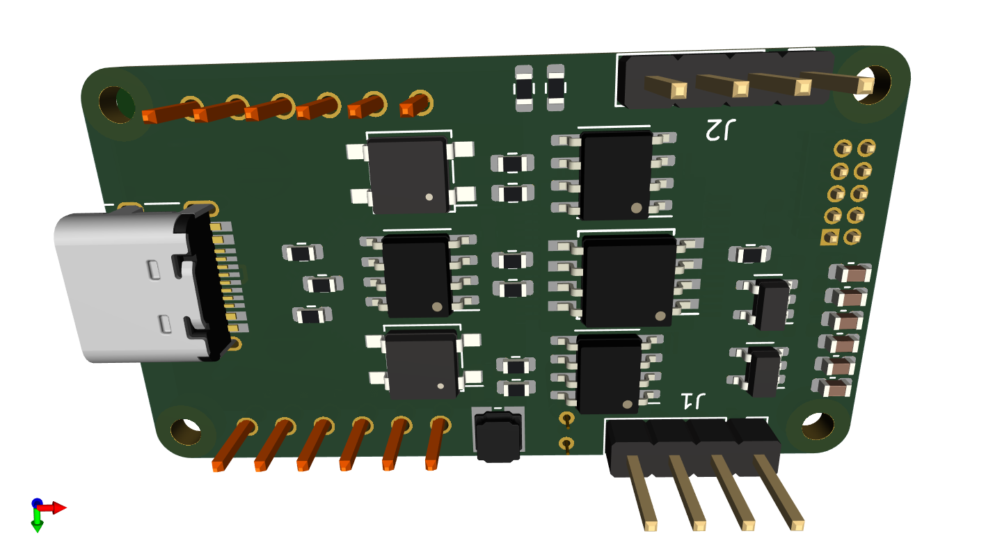
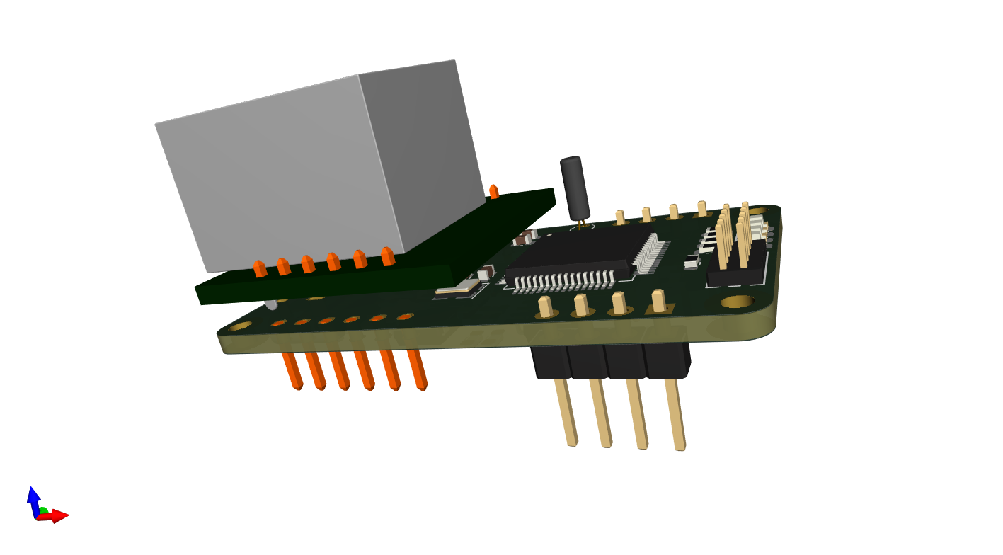
I have finished schematics, footprints, 3D models and placed the components and this starts to look good. The pictures below are exported directly from KiCAD. The Top layer contains the Ethernet module, MCU, crystals, leds and SWD. Only the 16Mhz crystal and some caps are under the Ethernet module. The bottom contains a USB-C connector, a CAN-FD Tranceiver, a RS485 Tranceiver, SPI Flash, SPI FRAM, 2 x SSR 120Ohm Terminal switches and 2 x separate PSU’s that connect if the coil is connected – one for the Ethernet module and one for the rest.
J1 is CAN-FD while J2 is RS485 connected to the motherboard allowing modules using both CAN-FD and/or RS485 to interconnect. I have yet to route this board and that will take me a few days, but I look forward to routing with 4 layers. As for ordering PCB’s – I get this ordered from JLCPCB and delivered in ca 10 days for ca 20.- USD – not bad. The BOM is 48 components so it is denser than it looks as it is only 25 x 45 mm. I excpect I might have to shrink the board to 24 x 44 mm, but I will return for that.
KiCAD 6.0.8 is great to work with containing many good improvements, but the library is in a bit of a mess loosing old footprints and 3D models. But, well – it is nice to be able to fetch components on the net and import them. STEP models can be found anywhere. For my usage KiCAD is great!
I am still using a few hole-though components because I want to use up my stock + I expect I have to do a few rounds on this. But, a bit of advice – hole through have to be assembled manually so they cost extra. The old fasioned 32Khz oscillator is okich here, but needs to be replaced – I have to think about headers. I want to replace SWD header with a PCB footprint that is excellent. But, well – that’s for later concerns.
In the early draft I considered using a TF Card, but I discovered that this MCU don’t support that. I did also reject the idea of multiple CAN ports and back to back connections and added a RS485 and a 3nd IPC alternative simply because that opens the option to use a long range of MCU’s. UART’s are available on all MCU’s.
I also added USB-C for the first time. It was only a few hours work to find a connector I could soldier and understanding what is what. The part I am most proud of is however the SW controlled 120Ohm termination on both CAN-FD and RS485. I actually fidured this out myself and got a reference design from a more experienced friend showing that I was on the right track. All in all this is actually a very dense, nice design.

