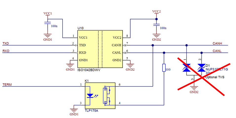
I recently discovered this chip (ISO1042) and wanted to share a circuit I found. This circuit is excellent, but it has two flaws:
Firstly you need a small isolation coil 10-20uH between ISO 1042 and VCC1. This act as a filter so that higher frequencies used by the buck converter in ISO1042 do not disturb the MCU. I need to check frequencies, but my previous experience indicate that a 10uH coil will do the job.
Secondly I have marked a red cross over D1 – This is a common way of protecting non-isolated CAN, but I have always been against it. Usually the tranceiver circuits can handle very hard pulses and are designed to deal with CANH and CANL beeing floating, differential signals. If you put D1 on you will be forced to include GND2 as the 3rd wire, but without D1 you only need CANH/CANL. In this case we use a galvanic isolated circuit that is far more capable that D1 and can handle pulses in KV area.
As for K1 (TLP175A) this is a nice way of making the terminator switchable through software. I have never bothered much about these, but it can be nice if you connect several devices in a network and need to select whom is switched on/off.
ISO1042 speaks for itself – it is 5 x 7mm, so this is a SOIC8, but notice that it has no external components except two standard filter caps on voltage. I am curious to test this and see how much heat it generate. I previously used chips from a different vendor and was a bit surpriced by the heat and noise from the buck converter.
Another feature on ISO1042 is that it is CAN FD (5Mbps) capable.
