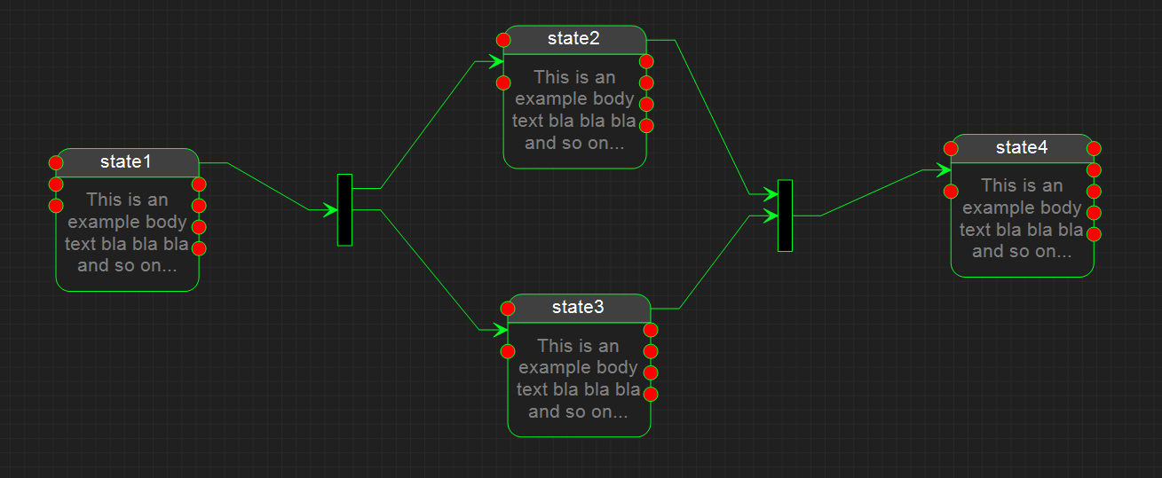
Just showing a test diagram on the UML State Engine Designer I am making. It is stoll lots of work and details left, but progress is actually going fast the days I work on it. As for now this is just an experiment. A state engine can visualize some top level flow, but the details of the logic get hidden. My plan is however to let users chose between sub-state diagrams or code editors and see if that works out. It is regardless a cool tool even now.
The red dots are pre-defined events – input on left and output on right. Red means they need to be connected. As they are connected the red dot disapear and is replaced with the connection line. One trick on a diagram like this is to automate lines to avoid that users spend time making lines look nice.
Keep in mind that this is an automation tool that will generate source code, it is not a drawing tool. That said precentation of readable diagrams into doc is one of the objectives.
Interaction with source code and/or PLD is straight forward. PLD is excellent for visualizing logic and will handshake well wil State Diagrams.
