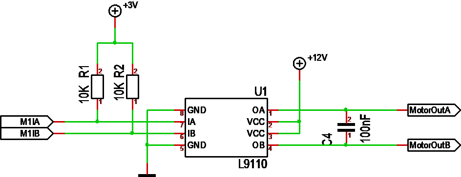
The second part of the Train control system is it’s motor driver. This is based on a classic L9110 H-Bridge chip. This allows us to drive a 500mA DC motor in both direction and we regulate speed with PWM duty. We need to return to speed adjustments later but we will be using the PWM signals on the ESP32 for this purpose.
This is where I went wrong on my previous version as I connected M1A and M1B to Inpu only capable ports. I discovered the error later as I tested the utility driver.
R1 & R2 is pull up’s that in this case is needed so the motor don’t accidentally start as we power up. C4 is to clip away DC motor noise.
