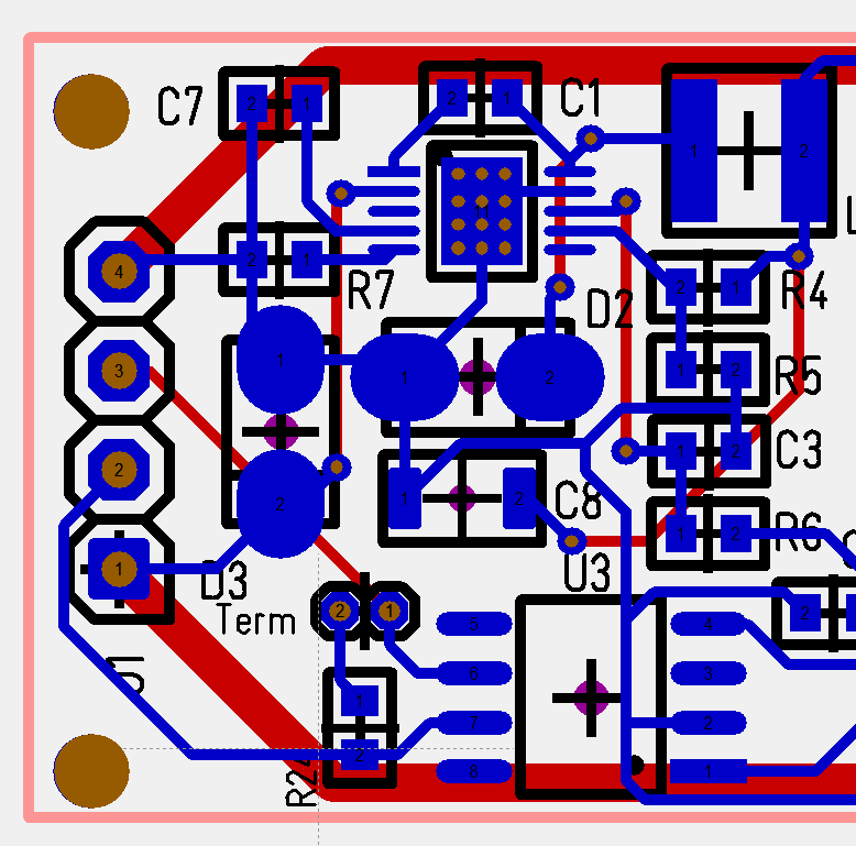
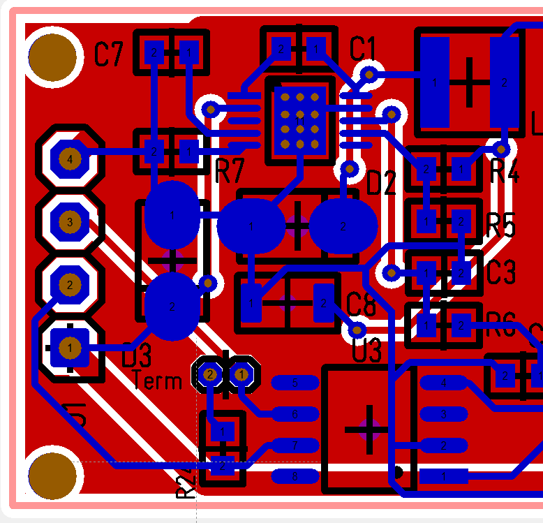
This just show the routing of the TPS54060 based DC/DC. The upper picture show the actual routing, while the lower show the real PCB once I add the ground plane. I still lack a few details to connect ground to the ground-plane in cases where ground is on a blue (top) lane. In this case I actually want to order with and without ground plane to see the difference on noise. This design is for 0.5A. I would need a larger coil for 1.5A or 2.5A. The components here are 0603 mostly, so the DC/DC area is ca 15 x 15 mm only. Learning from previous mistakes I need to add a scope test point because testing the DC/DC is one of the main objectives with this design.
Two of the resistors decide what voltage I want out which can be anything from 0.8V to 57V. I used Reference values a bit adapted, but might need to experiment to find E96 values for specific voltages. I am typically interested in 3.3V, 5V and 12V designs. I will add a separate DC/DC breakout with larger coil before I order this.

