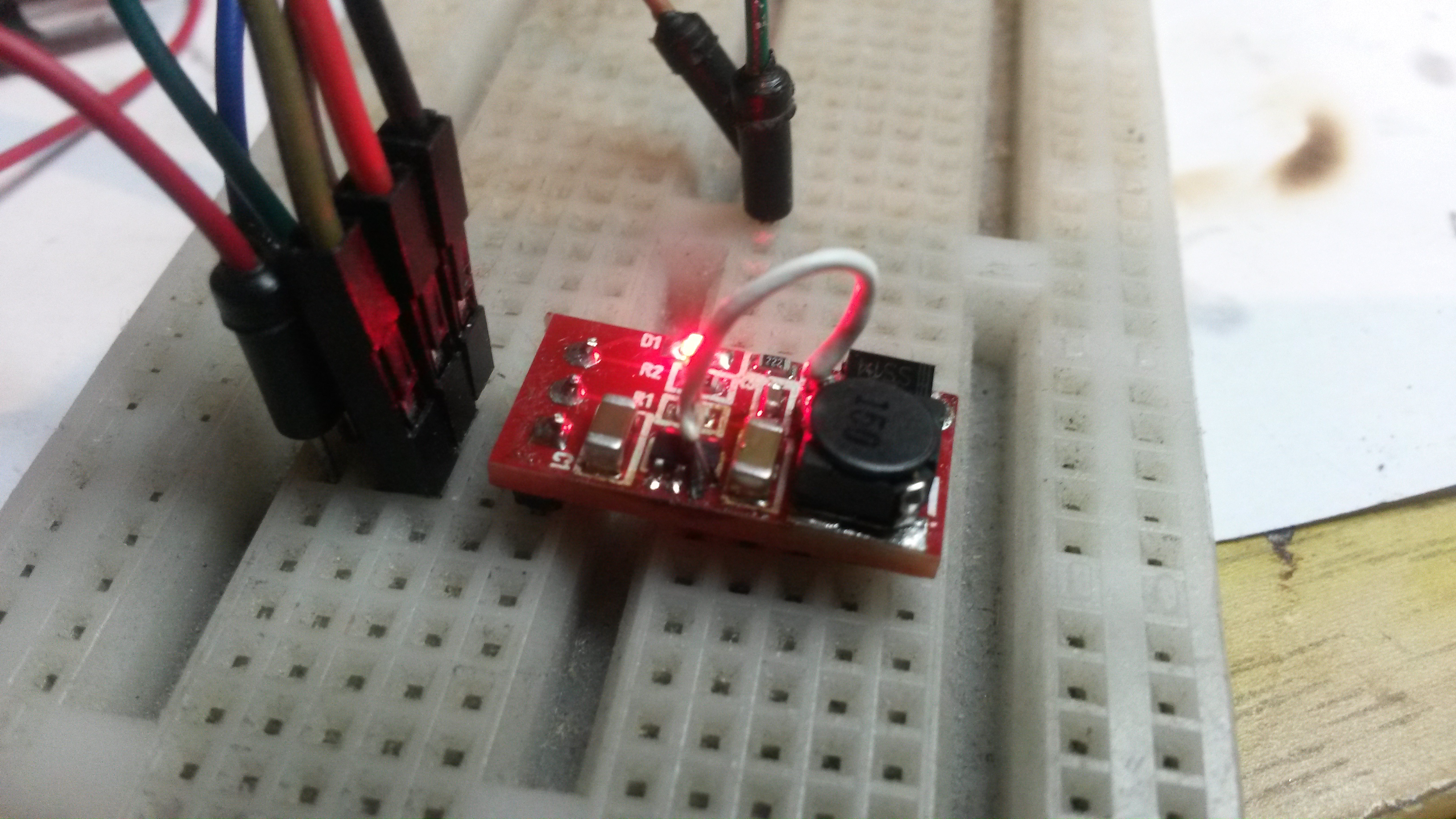
This is my LMR14206 DC/DC regulator with R1=15K and R2=1K which gives 12.2V out. The white wire is the PCB error I wrote about earlier.
This is basically only the reference diagram – just be aware that the datasheet and demo schemtics mess up R1/R2 a little. Myself I use E values, so by setting R2=1K I can adjust voltage out by changing R2.
You need ca 2V drop, so the input for 12V out is 14-42V. I will get back with updated schematics and values for 3V3 matching E24 series later. I also want to have a look at the ripple that need some improvements.
