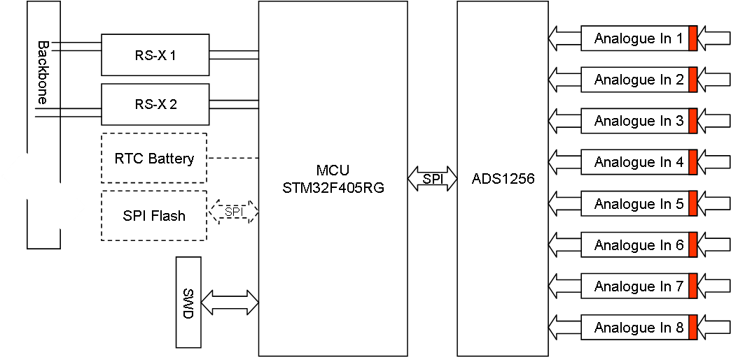
This analogue input module uses a ADS1256 that allow 8 channel input with 24 bit precision and 30Kbps sampling rate. With a programmable gain amplifier 1:64, programmable filter and support for single or differential inputs as well as calibration this board can cover most ADC needs.
The input here can be 8 stand-alone channels or 4 differential channels. A stand-alone channel will measure voltage between input and ground, while a differential channel measure voltage between two points. The later is more flexible as it also can be used for current loops. The challenge is however that different usage require different line adaption circuitry, meaning we will need different analogue boards.
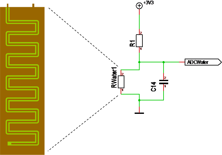
My primary focus is on typical analogue sensors like light, temperature etc. This example circuitry feed a voltage in that is split over 2 resistors with the sensor being the 2nd, variable resistor that changes with light, temperature etc. A typical ADC line driver is shown below:
This is the water sensor I illustrated earlier where we use a specialised PCB as a resistor. R1 need to scale the input so we get 0-3.3V out to the ADC. The capacitor is only a filter. More important is that we can Interface to this in two ways – we can create a 2 pin connector for the external resistor only, or we can supply +/- and expect an analogue value in. Many modern sensors will require the last 3 wire Interface as they provide their own specialised analogue interface.
The main drawback with this technique is that we can only have a limited distance between sensor and the ADC since the wire will start acting as a resistor that needs to be taken into account. A different analogue technique that can be used over 5km is a current loop – I will consider making a Board for that later. But, also remember that we have RS-X based sensors that can cover some distance in wiring.

