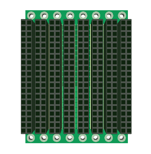
Just an update on the backbone board. I have decided to use a “All-In-One” central for home automation, but I still want to make a minimized PLC alike system. This backbone is very small – only 50mm width and 65mm height. The connectors are basically so tight with only ca 6.3mm apart that we are not likely to use every slot. I considered making it larger, but decided against it because the primary target here is mobile robotics. The connectors give me the option to use 1, 2, 3, 4 or even more slot width on a single card + I can add backbone board by having a board to board cable.
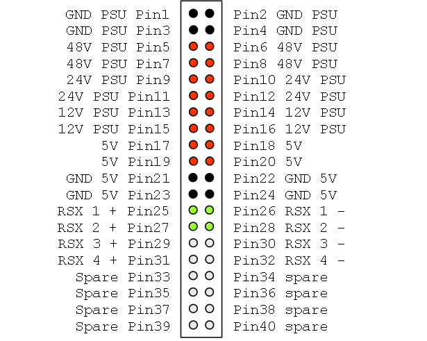
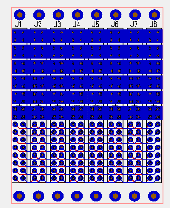
The main difference is that I ditched the A and B PSU signals and use a wider, combined lane to increase available ampere. I also add drill holes for each board. I am still a bit undecided about how I connect this to the PSU etc. I will be back on that.
This last picture illustrate the new power lanes. Wide tracks on both sides to support higher currents. The weak point is however how to connect this to a PSU. At present I would use a 40 pin connector and 4 cables per voltage – I need to think about that. One option is to add screw connectors etc. I will not order this board before I have a PSU design + some add-on boards, so we can let the ideas mature a bit.


